
| You are in: Instruments > MIR > Data Reduction |  |
 |
T-ReCS and Michelle Raw Data |
This page describes the raw data structure for T-ReCS and Michelle data (imaging and spectroscopy) in their commonly used observing modes, along with some discussion of different types of noise or instrumental effects one may see in these images. The basic modes of observation are discussed on the Mid-Infrared Observing page. See more information about:
Nearly all T-ReCS observations are taken in chop/nod mode, although a small number of specialized observations are taken in stare or stare/nod mode. Given the unusual nature of those observations, only the chop/nod mode will be discussed in detail here.
The basic feature of all ground-based mid-infrared observation is having a short exposure time, called the frame time, to avoid saturation due to the strong thermal emission from the telescope and the atmosphere. The frame times for T-ReCS filters are generally of the order of 25 ms, although the values range from about 8 ms for one of the longer wavelength Q-band filters to 80 ms for a narrow-band filter around 9 microns. The array is read out frequently and summed in a temporary buffer for each chop position. These buffers are read out as a saveset. One or more of these savesets are written out per nod position. In the raw data file there is one extension per nod position. If there are N savesets per nod, the image written for each nod has size [320,240,2,N]. The third image dimension selects the chop position. In nod position A this value is 1 for the on-source (guided) beam and 2 for the reference (un-guided) beam. In nod position B these are reversed, the index has a value of 2 for the on-source position and 1 for the reference position. T-ReCS nods in an ABABABAB pattern so all odd extensions are for nod A and all even extensions are for nod B.
The header keywords that are relevant to the exposure time and sky background in T-ReCS images, found in the primary fits header in extension [0], are the following:
T-ReCS raw data files have images of type integer, and as they are a co-add of a large number of frames the number of ADU per pixel can be quite large. A background level of several million ADU is quite usual. For example in taking a normal image of a bright target (actually a standard star) with the Si-5 11.7 micron filter, the number of savesets per nod was 3, the frame time was 25.8558006286621 ms (the precision here is excessive, and it is not clear exactly where it should be rounded off), the number of frames per chop position was 5, and the number of chop cycles per saveset was 28. One therefore has about 5 x 28 x 0.025856 seconds on target per saveset, and 3 of these per nod. This means 10.8595 seconds on target per nod. With 4 nods total in the exposure the total time on the source is 43.4381 seconds. The header gives the OBJTIME as 43.4376983642578 seconds, consistent with the value calculated (and again with excessive numbers of digits). The background level as given in the header is about 28300 ADU per frame. 140 of these frames are co-added per saveset, so the magnitude of the raw signal from the background is about 3.962 million ADU. The elapsed time is the NODTIME times the number of nods, or 161.626 seconds in this case, so the on-source efficiency is about 27%.
The T-ReCS detector saturates at 65535 ADU per frame, but there is a "detector clamp level" (given by the RDAEND, RDASTART, RDAMIN, and RDAMAX header values), so the available dynamic range per frame is roughly 58000 ADU; this background level is roughly 0.6 times the saturation level and the rest is available for observations of the target. While a very bright mid-infrared target may saturate the array, this is unusual. Most mid-infrared targets produce a much smaller signal than does the sky background.
An individual co-added image for one saveset and one chop position can be displayed in IRAF with a command such as
cl> display S20070703S0060[1][*,*,1,1] 1 zs+ nsample=76800
Just below is shown the resulting image as seen in the image
display tool. There is an object in the image but it is faint
compared to the sky+telescope background and is not visible in the raw
image.
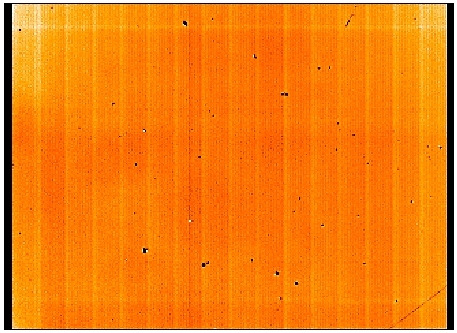
There are 16 read-out channels for the detector, which causes the image to have 16 vertical bands each 20 pixels wide as is seen in the image above. There may be small level shifts between the different channels, although these are generally small for T-ReCS images. The other obvious feature seen in the image is a number of bad pixels, mostly with lower sensitivity, that appear dark on the image.
When the raw data file is "prepared" via the tprepare task the savesets for each nod are averaged (either with registration or not) and the difference image is created from the on-source and off-source images. These are then stored in a image of dimension [320,240,3]. The last index has values 1, 2, and 3 for the on-source, reference, and difference images respectively. To display the difference image the command would be
cl> display tS20070703S0060[1][*,*,3] 1 nsample=76800
the result of which is shown just below.
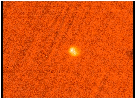
The object is visible in the field. For a single NOD one also sees the residual telescope radial offset, which appears in the above image as the bright/dark strips at an angle of about 24 degrees clockwise from the y axis of the image and as slightly fainter sgtripes at right angles to this direction. The direction of these strips changes with time as the telescope rotates to keep the image orientation on the sky fixed.
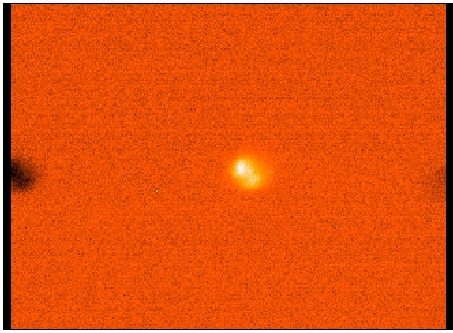
The telescope radiative offset is then removed by summing the nod A
and nod B difference images. Taking the difference images for
extensions 1 and 2 of the image being used as an example here and
adding them together produces an image that is shown below. The
background level is reduced from about 250 ADU to a small value near
zero. One also finds that the channel boundaries are not visible in
the summed image. The magnitude of the residual background depends on
the stability of the atmosphere during the period of observation.
With stable conditions over a pair of nods (roughly 1.5 minutes total
clock time) a good cancellation will result. When that is not the
case one tends to get a relatively uniform positive or negative
baseline in the images along with increased pixel to pixel variations.
When the individual nod difference images are combined to produce a stacked image pairs of nods are normally averaged together, and then these averaged images are in turn averaged together. If there is a problem with an individual nod (because of variable sky conditions, for instance) then it is necessary to remove that nod and the other nod of the AB pair from this process.
The negative beams in the stacked images are the two unguided images of the target. If in the future the guiding can be implemented in both chop beams using the two peripheral wavefront sensors then for those cases where two suitable guide stars are available the on-source efficiency can be doubled.
When a bright target is observed there may be artifacts in the raw data either due to the effect of transferring large amounts of charge over the array during read-out or due to cross-talk between the different channels. The most serious of these effects is a loss of response in a channel if a bright source is in the field. This is known as the "hammer effect". For a very bright source this will occur not only in the positive beam but will also be caused by the unguided images in the other chop position. T-ReCS uses a four-point sampling algorithm to reduce the hammer effect, although it is not entirely removed. If a very bright target is observed and the chop direction/amplitude is such that the object is located in the same channels on the array in both chop positions then the background level in those channels will be completely unreliable. Thus for bright sources it is a good idea to either chop in such a way that the target is off the detector in the negative beam or to chop along the long axis of the array to put the negative beams in different channels than those for the positive beam.
Bright targets also tend to have negative "ghost" images in adjacent channels. These cannot be removed by changing the chop properties. For a very bright source the ghost images can become negative streaks along the long axis of the array.
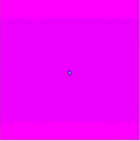
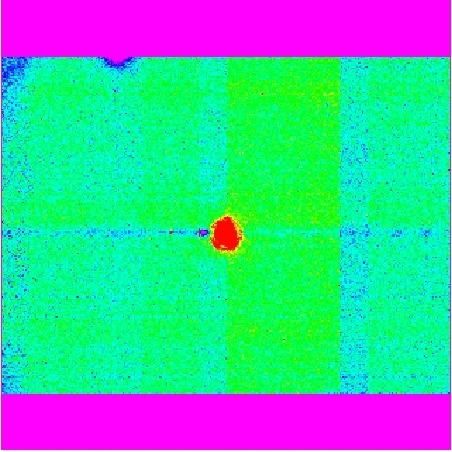
Below I show an example of an image of a bright compact source. The first image shows a display of the full intensity range (the chop angle is along the short axis of the array so the negative beams are not seen). The second image shows the display with the zs+option in IRAF. In the third image the range is set to +/- 6000 ADU to show the cross-talk between the channels more clearly. The IRAF commands for these three cases are:
cl> display rS20040104S0022[1] 1 zs- zr+ nsample=76800
z1=-8920.333 z2=1809739.
cl> display rS20040104S0022[1] 1 zs+ zr- nsample=76800
z1=-913.2543 z2=957.1675
cl> display rS20040104S0022[1] 1 zs- zr- z1=-6000. z2=6000.
z1=-6000. z2=6000.
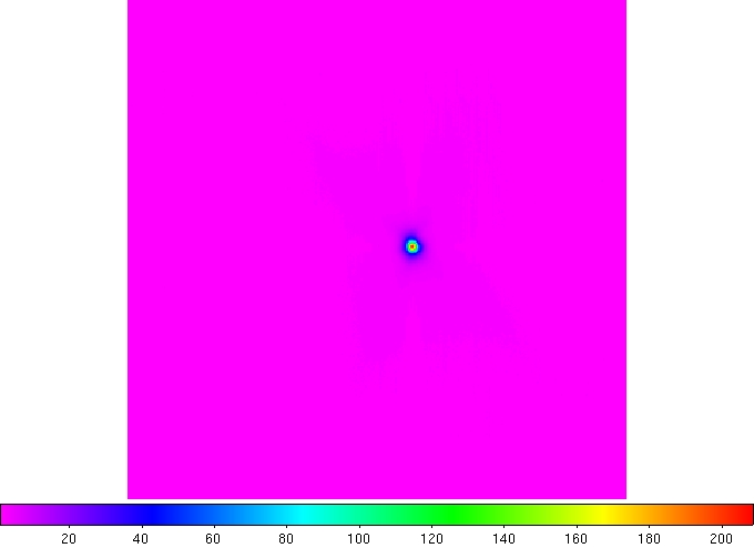
(The above image shows the entire ds9 display area, including the colour
bar, for reference. For all other images using the "rainbow" colour scheme
the same colour bar applies but the colour bar has not been included. Red
colour is most intense and the magenta/fuchsia colour is least intense.)
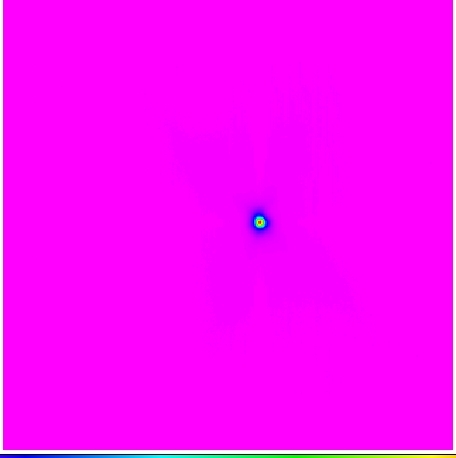
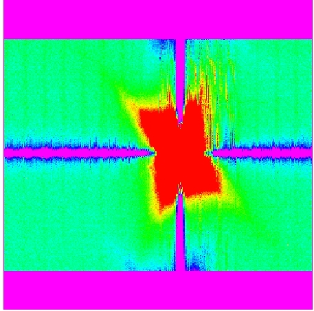
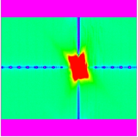
In the second image negative regions are seen extending up and down
the channel where the bright core of the object is situated and there are
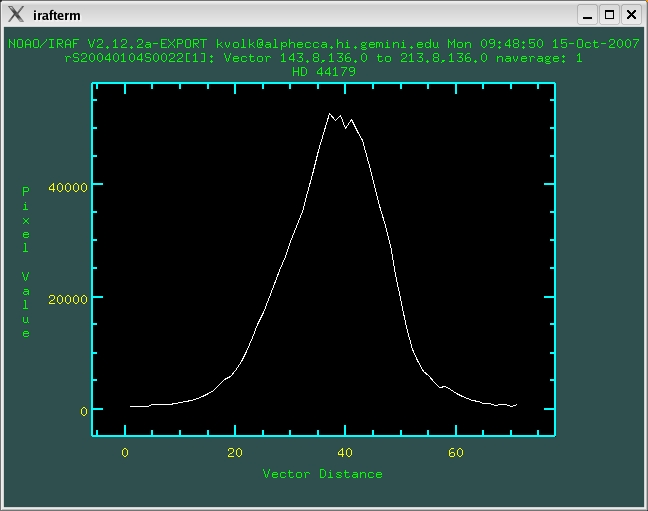
also negative streaks left and right from the core. A cut across the image
above the core shows the extent of the depression of the sensitivity in the
central channel. The peak of the profile should be smooth and go to a
sharp maximum, but instead one has the noisy pixels within +/-4 pixels of
the position directly above the core--pixel 40 in this plot.
There are other types of noise observed in T-ReCS and Michelle images. Some of these are specific to different filters. The most common sorts of such noise show up as either horizontal or vertical stripes in the difference frames. One such example is shown just below, an image of a standard star taken in the 10.5 micron [SIV] filter by T-ReCS. The stripes are seen when one looks at low levels in the image, hence the use of the zs+ flag in the display. The image was displayed in the following way:
cl> display rS20070703S0065[1] 1 zs+
Warning: setting CD3_3 to 1.
Warning: setting CD4_4 to 1.
z1=-109.4835 z2=159.237
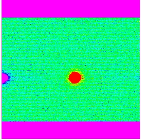
These sorts of pattern noise in the images are generally fairly easily removed using the miclean.cl task in the Gemini/IRAF midir.miutil package, since they are close to being uniform across the image. One also sometimes encounters similar noise patterns that are vertical on the array.
In principle T-ReCS observations can be taken in pure chop mode, stare mode, or pure nod mode. These modes are identified in the header and can be handled by the basic reduction scripts. In chop-only mode the file will have one extension with a large number of savesets, but otherwise be analogous to chop/nod mode. In the more unusual case where chopping is not used the dimensions of the raw image are altered to reflect the single chop position. Astronomers who may wish to use T-ReCS in any of these non-standard modes should contact the T-ReCS instrument scientist through the Helpdesk for technical evaluation of the suitability and practicality of such observations before any application for time is submitted.
T-ReCS spectroscopic observations, like imaging observations, are taken in chop/nod mode. The same data structure is used for these observations as is used in imaging. The smaller photon flux per pixel in this mode means that the hammer effect is only seen for extremely bright objects. One has the choice of chopping along the slit or perpendicular to the slit. In the former case one might see the negative spectra from the second chop position (depending on the angle and amplitude of the chop), while if chopping off the slit only the positive spectrum will be seen.
The telescope radiative offset is more difficult to see in the individual nods for this mode than is the case for imaging observations. The residual radiative offset is dispersed in wavelength and since typically all parts of the telescope in the field of view are at similar temperatures the emission tends to cancel out fairly well between the two chop positions. Even so one still needs to combine nod pairs to remove this background, and if a given nod is found to be bad the matching opposite nod should be removed from the data.
The image below shows a spectrum of a standard star taken with T-ReCS. In
this particular instance only the positive spectrum is seen because the star
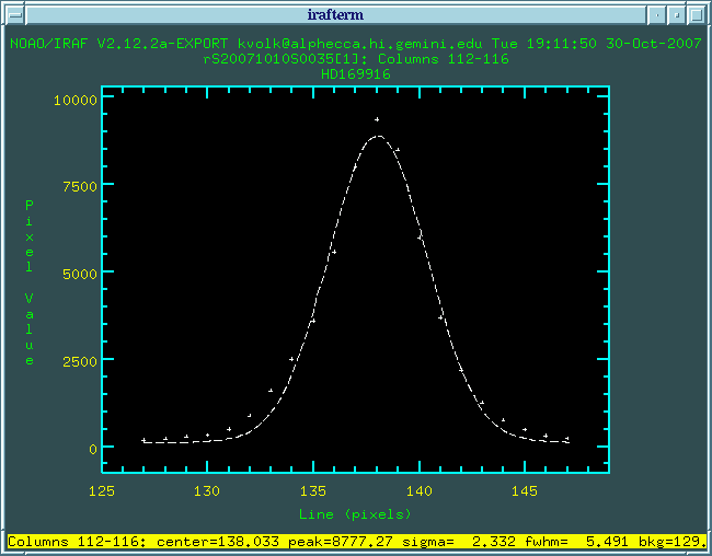
is off the slit in the other chop beam. The subsequent figures show a line
cut on the spectrum and the cross-profile of the spectrum. In this image
the wavelength increases from left to right across the array, while the
direction along the slit is along the shorter dimension of the array. The
particular example here shows low resolution N-band spectroscopy. A raw
low resolution Q-band spectrum shows a very different structure due to the
presence of strong atmospheric bands.
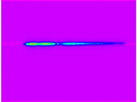
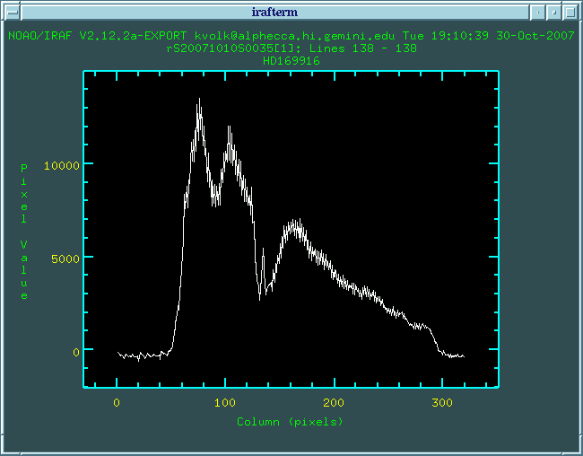
On the raw image and on the line cut one sees a lot of pixel-to-pixel structure. This is not noise as such, it is fringing in the spectrum. This is a common feature of all such mid-infrared detectors when used for spectroscopy. The fringing is a function of the slit width, the spectral resolution, and wavelength. For some unknown reason the fringing is much worse in the T-ReCS low-resolution spectroscopy mode compared to the same mode in Michelle. The fringes can be removed to some degree in the data reduction, using the msdefringe routine in the Gemini/IRAF package, but this removal is far from ideal in the higher resolution spectroscopic mode of T-ReCS and the analogous modes of Michelle spectroscopy.
The structure in the spectral direction is a combination of the filter
response and the atmospheric transmission. In the middle of the spectrum
around x=135 is a strong ozone band. Around x=90 there is another strong
dip in the spectrum which is due to a feature in the N-band filter response
(and which is unique to T-ReCS). At left and right, x less than 45 or
larger than 300, there is no spectral response due to cut-offs from the filter.
The plot just below shows a comparison of a raw T-ReCS low resolution N-band
spectrum to the expected spectrum of the star after transmission through the
atmosphere are this resolution. The ozone feature is obvious in the
transmitted spectrum plots, as are strong lines of water and other molecules
at wavelengths outside the filter passband. The raw T-ReCS spectrum is
shown with the y-axis scale at right, while the other three curves have
y-axis scaling as at left in this figure.
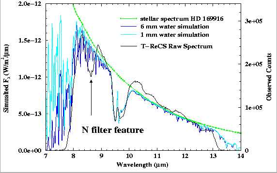
The ozone band is somewhat variable with time and direction, and since the band is so strong using a telluric calibration source to remove the band is essential in the data reduction for such N-band spectra.
In T-ReCS, as in Michelle, spectroscopic acquisition is usually done in chop-only mode. The images are of dimension [320,240,2,N] where N is some number of savesets.
Observations in the mid-infrared have high Strehl ratios (typical values are 35% in the short wavelength end of N-band, 65% in the long wavelength end of N-band, and 85% in Q-band; in very good seeing the estimated Strehl in the Si-5 11.7 micron filter can reach 85%). Under most optical seeing conditions the point spread function has full width at half maximum (FWHM) which is close to the theoretical resolution of the telescope. For Gemini at N-band with good seeing the FWHM in the Si-5 11.7 micron filter is usually near 0.35 to 0.37 arc-seconds (see the Observing Conditions Constraints page). In good conditions the FWHM tends to be roughly independent of the airmass -- as opposed to the case in the optical where the FWHM generally scales as airmass to the 0.6 power, in which case for stable seeing conditions the FWHM at 2 airmasses is 1.5 times what it is at zenith. At N-band one can have stable 0.35 arc-second FWHM seeing from the zenith down to two airmasses with very little change. Ideally the FWHM will be proportional to the wavelength through N-band and Q-band. In practice we see a somewhat flatter variation in seeing with the filter central wavelength (i.e., the IQ does not improve as quickly towards shorter wavelengths as would be expected from a simple scaling with wavelength).
Only under very poor optical seeing do we begin to see signifaicant atmospheric effects on the PSF at N-band and Q-band, whereupon the FWHM can become as large as 0.7 to 1.0 arc-seconds in the N-band filters (although this is relatively rare). In such cases where the bulk of the seeing is due to the atmospheric turbulence the FWHM begins to scale with airmass in the same way as the optical seeing normally does.
It is found that under the best seeing conditions at N-band or Q-band the Strehl ratio increases while the FWHM of the PSF does not change much. When the seeing gets somewhat worse the first indication is a loss of power in the PSF peak without significant change in the FWHM, followed by a broadening of the peak and a change of the shape of the PSF to follow a pure Moffat profile similar to what is normally observed with the (optical) GMOS instrument. Under better seeing conditions the PSF core is slightly better fit with a Gaussian profile than with a Moffat profile, although the difference is usually subtle.
Under good seeing the T-ReCS PSF shows several diffraction rings around
the central core. Generally the trefoil is prominent around the peak and
one or two outer diffraction rings can be seen in the image when a standard
star is observed under good seeing. An example of this is shown below. The
first image is a linear display of an image of alpha CMa zoomed in to the
star. It shows the trefoil around the core in a fairly typical manner.
The second image shows a the full frame of another observation of the same
star on a different date with very good seeing (note that the orientation
of the trefoil has changed...), where the image maximum is reduced by a
factor of 5 from the peak value to highlight the low-level structure in
the PSF. The third image is the same as the second image only zoomed in
somewhat to show the structure better.

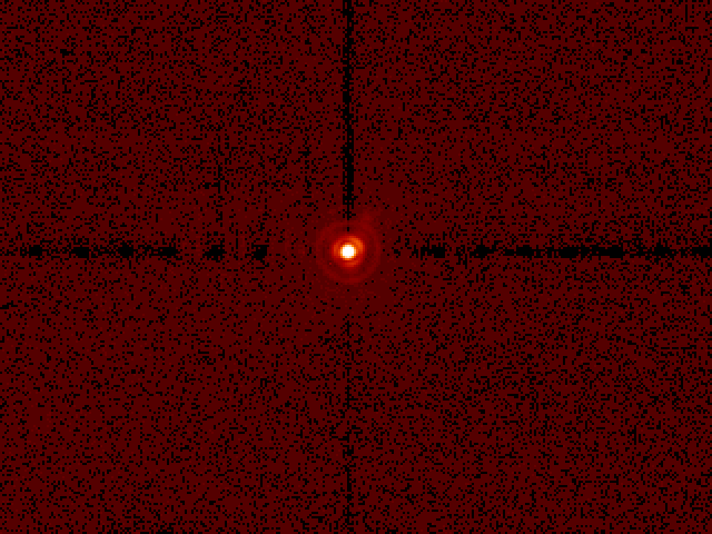
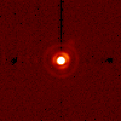
The three-fold symmetry in the inner diffraction ring, trefoil, is typical of mid-infrared images on Gemini. When the PWFS2 is used for guiding the trefoil is not corrected for. In the less usual case where PWFS1 is used to guide the wavefront sensor sends trefoil corrections to the telescope and this trefoil structure is removed. The trefoil tends to be stronger in the early T-ReCS data (to 2005) but has been less prominent in more images since 2007. As most of the T-ReCS examples here are drawn from older images the trefoil is often quite obvious.
For this image there is a filter ghost north-north-west of the core at
about 2 o'clock just outside the second diffraction ring. Although it is
only faintly seen by eye in the above images, there is also a third
diffraction ring in the image. Making a radial plot of the PSF allows one
to see the diffraction rings as is seen below.
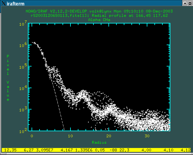
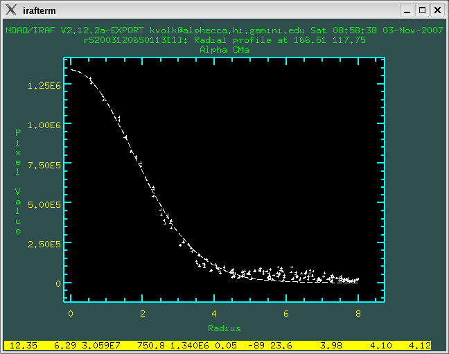
The core FWHM is 4.12 pixels = 0.37 arc-seconds. The trefoil produces the first bump on the profile outside the core at radius about 6 pixels. The next diffraction ring is at radius 13 pixels and there is another at radius 20.5 pixels. The more diffuse peak at radius 17 pixels corresponds to the filter ghost. There may be another much fainter diffraction ring at radius 32 pixels, although this is marginal at best.
The way the radial profile looks using the default IRAF rimexam
parameters is shown just below. In such a plot one sees the core and the
trefoil components.
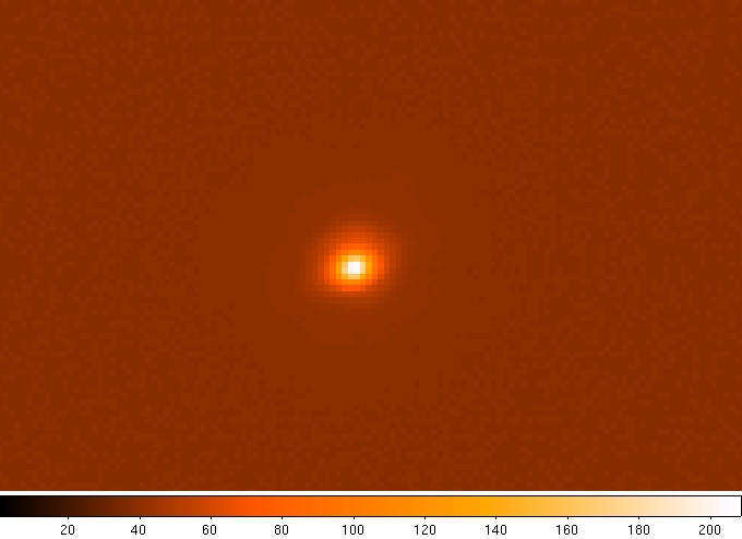
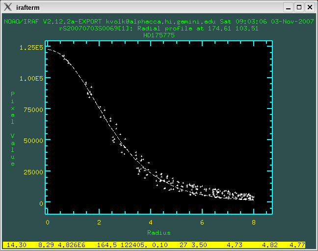
An example of the PSF and the radial profile under poorer seeing
conditions (definite optical
IQ=85% conditions) is shown below. The FWHM is now about 15%
larger than it would be in good seeing, and the radial profile follows
the Moffat profile fairly well over the range of the plot. One no
longer sees the trefoil due to the poorer intrinsic seeing conditions.
There is also some odd low level structure in the PSF and the
ellipticity is higher than it usually is in good seeing (e=0.10 here
compared to e=0.05 for the alpha CMa image above in good seeing). As
long as the PSF is stable over the time of the observation images of
extended targets can be deconvolved even with a poorer PSF like this
to get a good reconstructed image.
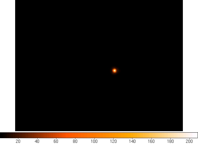
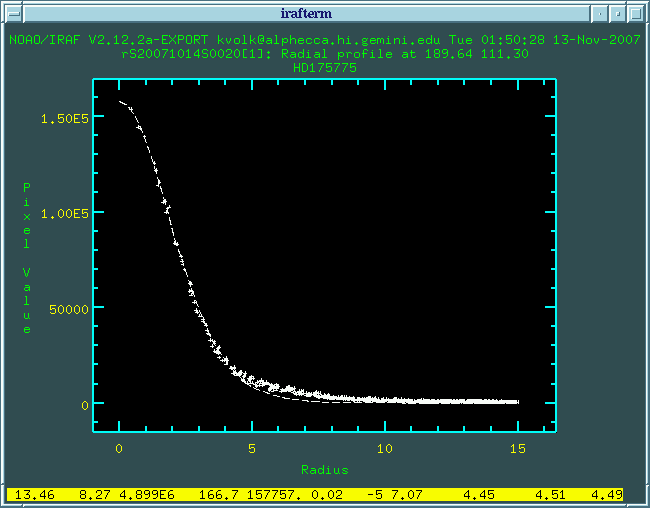
For comparison consider the following two PSF profiles. The
first case is for the same object as in the above example, under
average to a bit worse than average seeing in N-band: the FWHM in
the 11.7 micron Si-5 filter is about 0.40 arc-seconds which
is not as good as is often observed (values down to 0.37 arc-seconds
can be obtained in better seeing conditions), but the estimated Strehl
is 0.54 and one can see the prominent trefoil around the core of the image.
The radial profile is shown after the image below. The trefoil causes the
radial profile to be above the Moffat fit from about 4 to 9 pixels radius.
This is the general type of profile expected under IQ=70% conditions in the
mid-infrared.
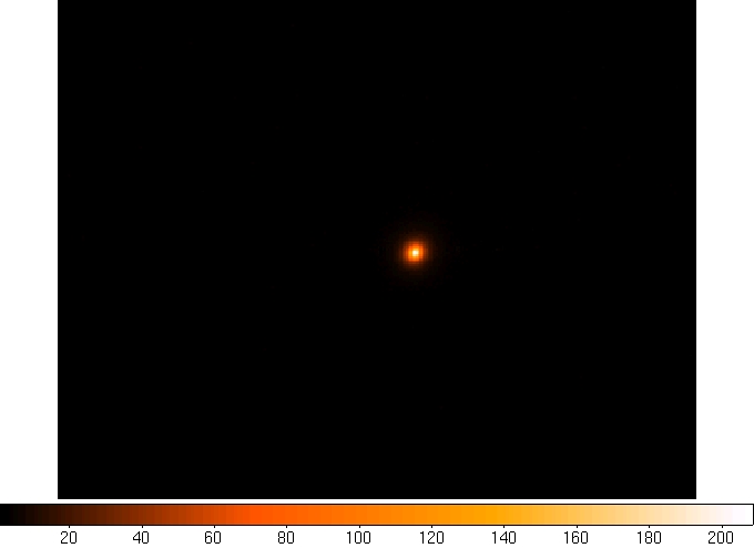
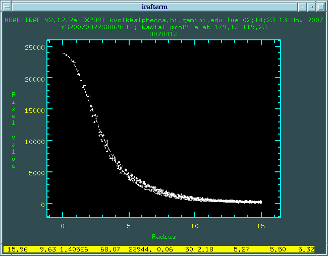
Under poorer seeing conditions, IQ=85% in the mid-IR, and with the same
filter the PSF and profile look more like the example given below. The
FWHM has increased to 0.48 arc-seconds, while the estimated Strehl has
decreased to 0.28, only about half the value in the case just above. When
the optical seeing is extremely poor one may get FWHM values of the order
of 1 arc-second in N-band. As noted above, in such poor seeing conditions
the PSF scales with airmass in a way similar to what is normally the case
in the near-infrared and the optical.
Michelle operates very similarly to T-ReCS, so most of the features of the raw and stacked data files are very similar. One significant difference between the two instruments is that Michelle data are saved at the end of one full nod period, roughly 40 seconds in most cases (no savesets are used). Michelle imaging and low resolution spectroscopic observations are taken in chop/nod mode as is also the case for T-ReCS. However the higher resolution spectroscopic modes of Michelle are taken in pure nod mode without chopping, which is quite different than the case for T-ReCS.
In chop-nod mode the Michelle raw data files have images for the two chop beams and a difference image right at the start. Thus the image format of each extension of a raw Michelle file is [320,240,3,1]. The last dimension is degenerate and only present so that T-ReCS and Michelle raw data images have the same dimensionality. In the raw data the third dimension has values 1 for the difference image, 2 for chop position A and 3 for chop position B. The difference is always chop position A minus chop position B, so the difference changes sign from the A nods to the B nods.
The header keywords concerning the exposure time for Michelle are the following:
The time on-source in the guided beam is given by the frame time multiplied by the number of exposures. The total time for the exposure is also given as the OBSTIME header keyword, so the on-source efficiency can be calculated if desired from these values. An example image with the 11.7 micron Si-5 filter has an EXPOSURE value of 0.09 seconds, a NUMEXPOS value of 144, a NUMEXT value of 8, and an OBSTIME of 365.999221801758 seconds. The total time on source is 0.09 x 144 x 8 seconds = 103.68 seconds. The on-source efficiency is therefore about 28%.
One distinct difference between Michelle data and T-ReCS data is that in Michelle the frames within a nod are averaged rather than co-added. The data type of the raw data files is real numbers rather than integers. The raw background per chop position is seen in the raw images directly. For Michelle saturation occurs at around 52000 ADU so the raw sky background should be much lower than this (roughly half full well in average weather conditions) to preserve a good part of the detector dynamic range for detection of the object.
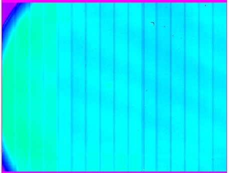
An on-source raw image is shown below. One thing that is seen right off
is that there is a vignetted region in the left corners, which is true for all
images taken by Michelle. The same 16 channel structure is seen here as in
T-ReCS raw frames, but the channel to channel offsets are somewhat more obvious
than is the case for T-ReCS. Michelle does not use four-point sampling when
reading the array out. The following line cut across the raw image shows
the channels quite clearly. Each group of four channels from left to right
has a separate read-out channel and thus tends to be offset from the other
groups. The channel offsets can be removed by taking a bias frame (although
that is not normally done except for spectroscopic observations) or by
software. The miclean.cl task generally is able to remove the channel
offsets from Michelle images. In most cases the channel offsets are much
reduced in the difference images.
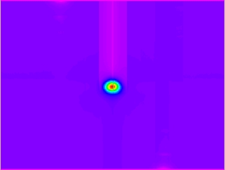
The hammer effect is typically much more of a problem in Michelle images
than in T-ReCS images, again due to not using four-point sampling of the
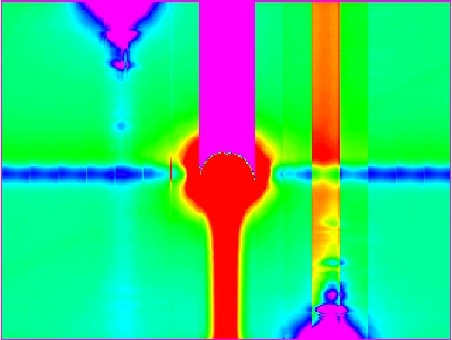
array during read-out. A rather bad example of the hammer effect is shown
below where an image was taken of an extremely bright mid-infrared source,
IK Tau. The hammer effect up the columns in the middle are at the 3% level
compared to the peak on the target. The second picture shows the same image
with the zs+ option, whereupon the hammer effect from the negative beam
at right is clearly seen. (There is no hammer effect from the other negative
beam because the source is at the top of the columns.)
In the difference image one does not see the vignetted regions in the left corners because the general background level is near zero. However if the background becomes high enough to saturate the raw images the shape of these vignetted corners tends to be seen in the Michelle difference images, and hence in the stacked difference image.
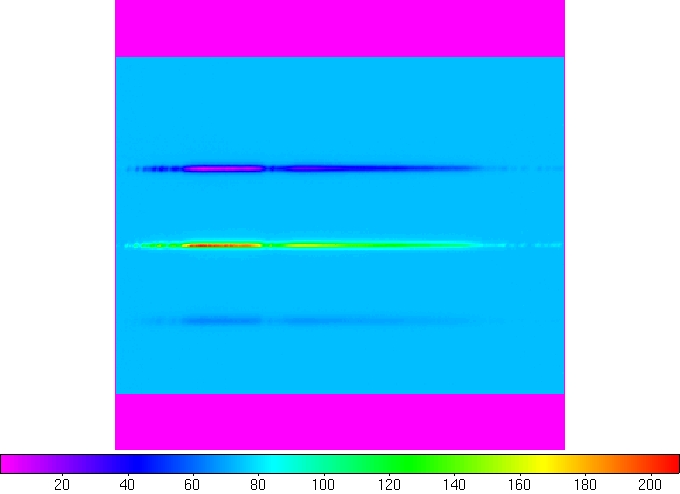
A raw Michelle low resolution N-band spectral frame is shown below.
In this case the star is chopped along the slit, and the two negative
spectra are seen. For reasons that are not yet understood the lower
of the two negative beams is generally much weaker than the upper one,
whereas normally one would expect the two to be of the same strength
and each about half the strength of the positive spectrum.
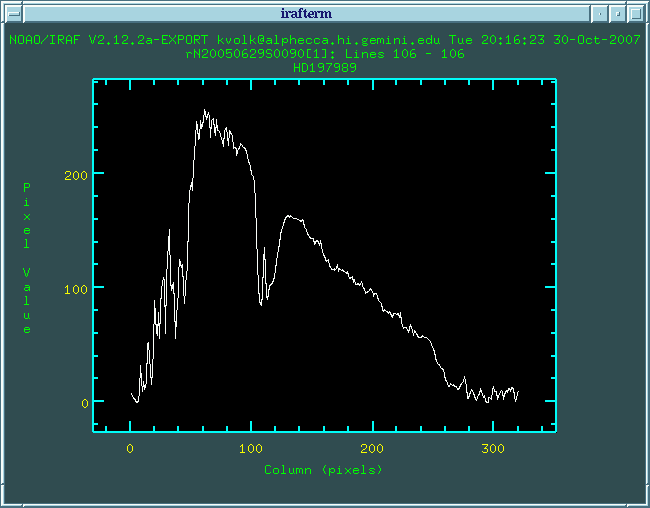
A cut across the spectral image shows a fairly similar ozone band structure
as is seen in the T-ReCS raw spectral cut above--note however the lack of
fringing. As Michelle uses a long-pass filter which cuts on at about 7
microns when doing low resolution N-band spectroscopy, when conditions are
dry there is some spectral signal over most of the array. The structure
in the cut on the left-hand side reflects water bands in the atmosphere. On
the right-hand side of the array there is only very weak signal. While the
filter passes radiation beyond 13 microns, there is strong atmospheric
emission at these wavelengths in addition to radiation from near 7 microns
coming in at second order. As a result, Michelle is unable to detect
the spectrum much beyond 13.5 microns, although it does have slightly better
long wavelength coverage than T-ReCS does.
The polarimetry mode of Michelle produces a different type of raw data
file. Each extension contains the images for one nod position, but within
the extension there are images for several waveplate positions. The
current mode of observation is to have eight waveplate positions observed
per nod -- at waveplate angles of 0, 45, 45, 0, 22.5, 67.5, 67.5, and
22.5 degrees. The images from each waveplate position have the same
structure as in normal imaging mode, [320,240,3], and when written out
to the raw data file the eight images are combined into an image of
dimension [320,240,3,8] where the last dimension is the index of the
waveplate positions. The purpose of having eight waveplate positions
per nod in this manner is to take out any linear drifts in the system,
being directly analogous to ABBA nodding. However the efficiency is low
due to the frequent changes of the waveplate position per nod (the nods
are longer than in normal imaging mode, but only by about a factor of 2
so the time per waveplate position is quite short).
Once a raw Michelle polarimetry data file is processed with the
mprepare task in the GEMINI/IRAF package the images for each
waveplate position are split out into separate extensions.
The same types of pattern or other noise are seen in Michelle images
as are seen in T-ReCS images. The channel to channel offsets are usually
more obvious in Michelle stacked images than in T-ReCS ones, but the
miclean.cl routine removes these offsets quite well so this is not
usually an issue. The various types of stripe noise seen in T-ReCS
images are also seen in Michelle images, although they are rarer in general
(possibly because T-ReCS has a much wider selection of filters than does
Michelle, as many of these types of noise are filter-specific).
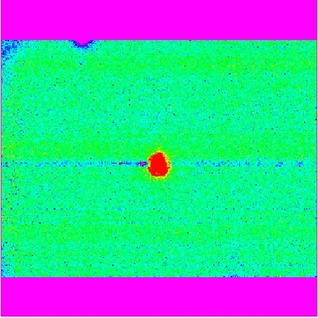
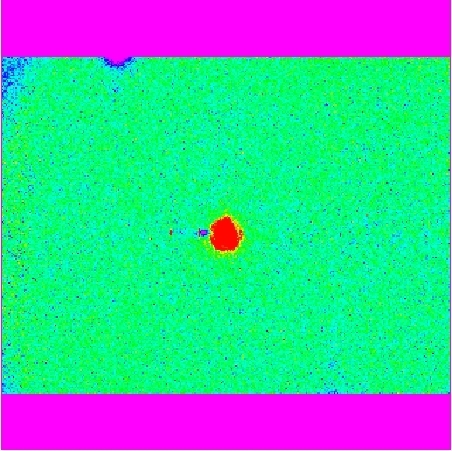
The figures below show in turn (a) a stacked image of a fairly bright
standard star displaying the full intensity range, (b) the same image
showing only the range of pixels near the median, in which one sees small
channel offsets which we call "staircasing", (c) the same image after the
channel to channel offsets are removed with miclean.cl, wherein
there is some banding across the image from left to right, and (d) the
same image again after the horizontal noise is removed with miclean.cl.
One can see that the systematic background is removed rather well by the IRAF
script. The various commands used in IRAF for this are:
Polarimetry Mode
Noise in Michelle Images
mi> display rN20050528S0202[1] 1
z1=-16.23066 z2=1127.012
mi> display rN20050528S0202[1] 1 zs+
z1=-2.69346 z2=6.610248
mi> miclean rN20050528S0202 fl_stair+ fl_rows- fl_col-
MICLEAN
MICLEAN -------------------------------------------------------------------
MICLEAN Log opened at [Wed 09:11:36 31-Oct-2007]
MICLEAN
MICLEAN --------------------
MICLEAN Input Parameters:
MICLEAN      inimages       = rN20050528S0202
MICLEAN      rawpath        =
MICLEAN      outimages      =
MICLEAN      outpref        = c
MICLEAN      fl_stair       = yes
MICLEAN      fl_columns     = no
MICLEAN      fl_rows        = no
MICLEAN      fl_simage      = no
MICLEAN      stairpref      = s
MICLEAN      fl_nimage      = no
MICLEAN      noisepref      = n
MICLEAN      threshold      = 3.
MICLEAN      logfile        =
MICLEAN      verbose        = yes
MICLEAN --------------------
MICLEAN Processing 1 image(s).
rN20050528S0202.fits[0] -> crN20050528S0202.fits
MICLEAN --------------------
MICLEAN Exit status: SUCCESS
MICLEAN Log closed at [Wed 09:11:37 31-Oct-2007]
MICLEAN -------------------------------------------------------------------
MICLEAN
mi> display crN20050528S0202[1] 1 zs+
z1=-4.01059 z2=4.040272
mi> miclean crN20050528S0202 fl_stair- fl_row+ fl_col-
MICLEAN
MICLEAN -------------------------------------------------------------------
MICLEAN Log opened at [Wed 09:12:31 31-Oct-2007]
MICLEAN
MICLEAN --------------------
MICLEAN Input Parameters:
MICLEAN      inimages       = crN20050528S0202
MICLEAN      rawpath        =
MICLEAN      outimages      =
MICLEAN      outpref        = c
MICLEAN      fl_stair       = no
MICLEAN      fl_columns     = no
MICLEAN      fl_rows        = yes
MICLEAN      fl_simage      = no
MICLEAN      stairpref      = s
MICLEAN      fl_nimage      = no
MICLEAN      noisepref      = n
MICLEAN      threshold      = 3.
MICLEAN      logfile        =
MICLEAN      verbose        = yes
MICLEAN --------------------
MICLEAN Processing 1 image(s).
crN20050528S0202.fits[0] -> ccrN20050528S0202.fits
MICLEAN --------------------
MICLEAN Exit status: SUCCESS
MICLEAN Log closed at [Wed 09:12:36 31-Oct-2007]
MICLEAN -------------------------------------------------------------------
MICLEAN
mi> display ccrN20050528S0202[1] 1 zs+
z1=-3.788237 z2=3.82229
For the Michelle low-N and Low-Q spectroscopic modes the observations are taken in the same chop/nod mode as imaging observations, although with a rather lower chop frequency of about 1 Hz rather than 3 to 4 Hz as for imaging. However all the higher resolution Michelle spectroscopy modes -- medN1, medN2, and echelle -- are taken in the same way as near-infrared spectral observations: nodding along the slit to remove the background emission, rather than chopping and nodding.
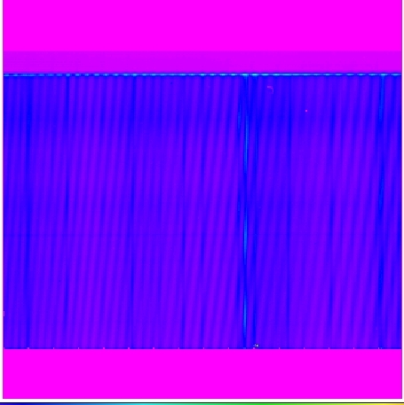
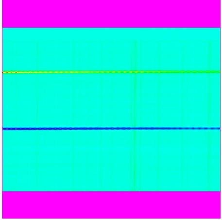
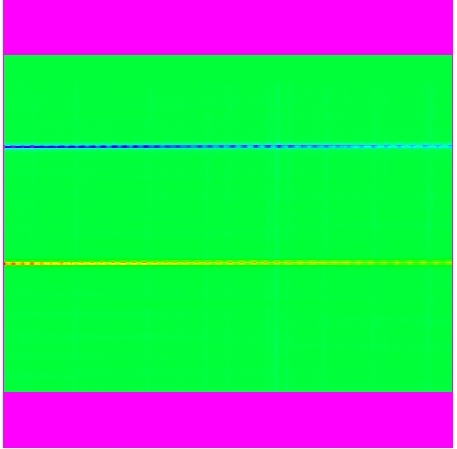
The individual file extensions in the raw data have dimension [320,240,1,1] so the last two dimensions are degenerate. This is done to keep the same number of dimensions as in the chop/nod mode case (which in turn has the extra dimension to match the T-ReCS raw data files). Just below are shown a raw image of a medN1 spectrum with central wavelength of 11.5 microns. The star is much fainter than the background. On the raw image one sees two things: the atmospheric emission lines which are almost straight along the y axis of the image, and the fringes which in this case are tilted slightly clockwise from the y axis. There is an un-illuminated region at the top of the array, this is normal in the higher resolution spectral modes of Michelle where a steeper grating tilt is used.
The next image shows the simple difference of the first two nod positions,
where the positive and negative stellar spectra are visible. There are still
some residual sky lines visible due to small variations in the conditions
during the two nods. These tend to disappear when more nods are stacked
up, in part because any linear time trends in the sky line strengths
are taken out by the ABBA nod pattern. After that the stacked image is shown.
In this case there is very little in the way of residual sky emission. The
case where residual lines are more likely is where lines are saturated in the
exposures. The region of N-band in this spectrum is mostly clear of very
strong lines, so this effect is not particularly evident here. Where these
lines are present no signal is received anyway, so it does not matter that
there is some residual signal (the residual signal is due to variations in
what part of the core of the line is saturated, and can leave either
positive or negative residuals depending on how conditions change during
the observation).
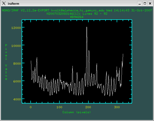
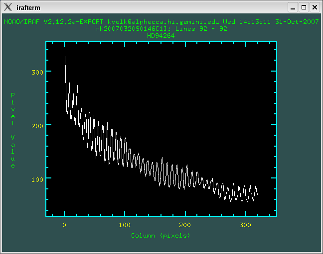
The magnitude of the sky emission and the fringing is shown in the
lines cuts below. The first one is a line-cut at the source position in
the raw image above. The following plot shows the same line cut in the
stacked difference image. Note the change in total intensity and that the
fringes are not removed in this process. All of, or nearly all of, the
high frequency structure seen in this spectral cut is due to the fringing.
Unfortunately the fringing signal does not appear to have a simple Fourier
signature that can be removed easily from the spectrum.
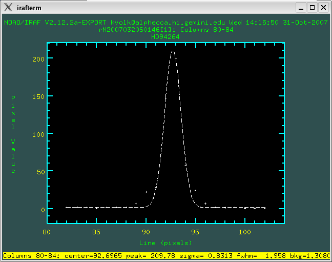
Finally, the plot below shows a profile across the spectrum along the
slit direction. This is fairly typical of Michelle spectra.
In most cases spectroscopic acquisitions for Michelle are done in chop-only mode, which is treated like a single nod of a normal chop/nod observation. Thus the background radiative offset of the telescope is present in these images. The only other matter of note for these observations is that the orientation of the field is rotated 90 degrees from the standard orientation, so north is to the left and east is down on the array.
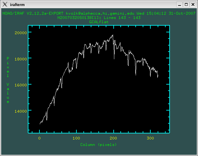
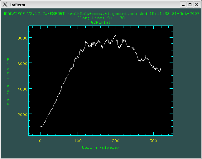
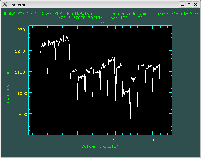
When spectral observations are taken Gemini provides a flat image and a bias image to aid in the spectral data reduction. These are taken in simple stare mode. The image dimensions are the same as for nod mode, since it is treated like a single nod observation. The flat is made by having Michelle look at an internal surface which is at nearly ambient temperature, so to a fair approximation the spectrum is that of a blackbody at roughly 0 degrees Celsius. In low resolution N-band or Q-band modes the brightness changes a fair amount over the array. In all the higher resolution modes there is not much spectral structure in the flats. The third image is the difference between the flat and the bias image. This should in principle be the pure spectrum of the surface. It does have some structure still present, presumably due to the material in the surface being looked at.
A line cut through the flat is shown below. There is some structure
that is seen on the cut, aside from the overall spectral rise and
turn-over. The second line cut shows the residual structure after the
bias removal. A line cut from the bias is also shown as the last plot,
wherein one sees the staircasing between the channels.
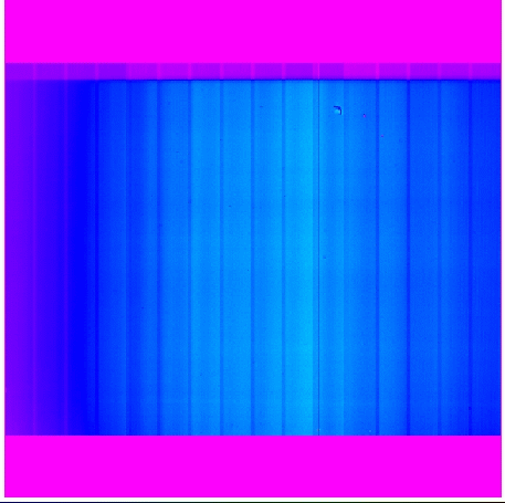
A low-N flat image
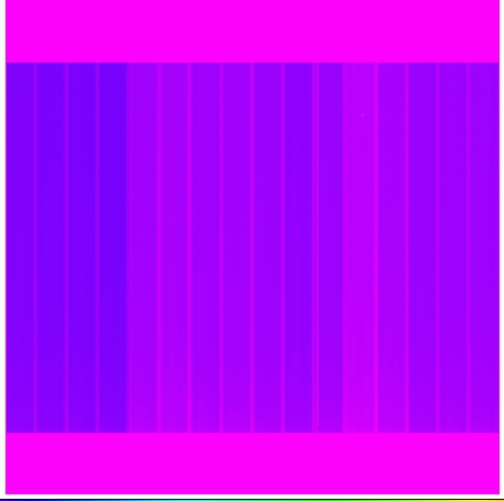
A bias image
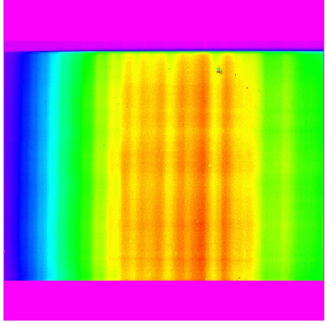
A low-N bias-subtracted flat image
In general terms all the comments about the T-ReCS PSFs apply to the Michelle PSF as well. The Michelle pixels are slightly larger as projected on the sky than the T-ReCS ones (0.1005 arc-seconds across compared to 0.08976 arc-seconds across) which makes small differences in sampling but otherwise the PSFs nominally have the same characteristics as for T-ReCS.
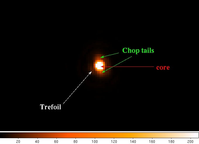
However there is a problem with the Michelle PSFs that is not observed with T-ReCS and which appears to be a telescope guiding problem rather than a problem inside Michelle itself: the PSFs have a tendency to be elongated in the chop direction. These elongations are colloquially known as "chop tails". They cause the typical ellipticity of the Michelle PSFs in good seeing conditions to be e=0.15 to e=0.20 as measured in IRAF, compared to typical values e=0.05 in cases where the chop tails are not seen in Michelle observations. Examination of the individual nod images when the chop tails are present show that the elongation is in the negative chop direction for each nod position, so that when the A and B nods are combined the result is elongation on both sides of the core of the PSF. The cause of these chop tails is not yet understood, and while the chop tails are not always present it appears that the frequency of occurrence of the chop tails has increased with time from 2004 through 2007. Early on only a small fraction of images were affected by the chop direction elongation, whereas by semester 2007B almost all observations have this problem.
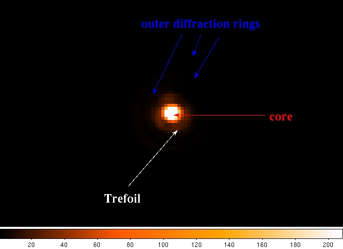
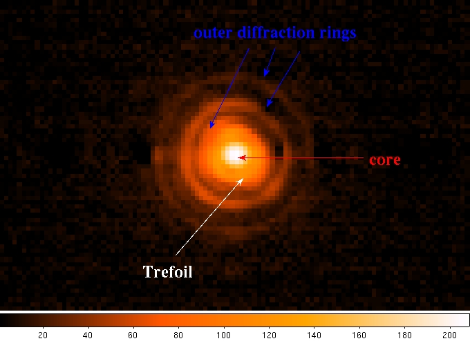
An example of the PSF one obtains with the chop tails problem is shown below. This is from an image taken under good seeing conditions on September 14, 2007. One sees the core, the usual trefoil and first diffraction ring, and a second fainter diffraction ring (the figures also label another "diffraction ring" between the trefoil and the first complete outer diffraction ring, but this may be an extension of the trefoil due to the chop tails). The core is seen to be somewhat elongated, close to along the y axis of the plot which is the chop direction in this observation. The nominal angle from the PSF fit is -9 degrees E of N, slightly off of the chop direction (which is also typical of this problem). The images below show the PSF in a linear plot, in a logarithmic plot, then with the features marked. The last figure shows a radial profile for the star, and the blue arrows mark the diffraction rings. As this source is 3.5 times fainter than alpha CMa (42.6 Jy compared to 143.1 Jy in the IRAS [12] filter) the peak to background ratio is smaller than in the example radial profiles for T-ReCS above. It is a good idea to use somewhat fainter stars with Michelle because the hammer effect is worse than with T-ReCS.
The ellipticity of the image core is e=0.10 from IRAF. This is at least twice what it should be under these seeing conditions. In worse cases the ellipticity can be 0.2 or sometimes higher due to the chop tails. There is some evidence that the chop tails are mimimized when chopping east-west and are stronger when chopping in other directions, but this is yet to be rigorously tested.
The flux level of the outer diffraction ring in the PSF images is about
0.00015 times the raw background sky flux. Nonetheless it is visible in
one ABBA nod cycle. The peak of the stellar PSF for this object of
brightness 28.38 Jy in this filter is still 8 or 9 times less than
the background radiation in a raw frame. Calibration of this image implies
a sky brightness of roughly 1700 Jy/square arc-second in the Si-5 filter,
and a brightness of 0.24 Jy/square arc-second in the outer diffraction ring.
If mid-infrared observations are taken under variable cloud conditions, or if some object is blocking the field of view, the raw Michelle or T-ReCS images may be saturated. While the observer at the telescope would be expected to see that the image is saturated, and usually to flag it as "fail", in this section a discussion is given of how to detect saturation of the images. If only a few nods in a long observation are saturated the observation may be set to "pass", either because the saturated nods were not seen at the telescope or because the conditions are consistent with what is requested (CC70 or worse conditions may well result in some saturated data, especially in imaging mode). Normally an observation would not be passed if a wavefront sensor, or some other unusual part of the telescope, is in the beam, but there are rare exceptions to this as well.
The example image used to illustrate the effects of saturation here is one
where the only PWFS2 guide star available is only 3.67 arc-minutes from the
target position. In the OT one finds that the outline of PWFS2 on the image
display overlaps on the image of the field (see below). The outline in the OT
image widget is quite accurate, although the affected area is slightly larger
than would strictly be expected from the shadowed region shown.
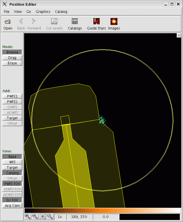
In this instance since no other guide star was available and since the
target object was expected to be point-like the sky rotation of the image
was selected to minimize the shadowing of the field by the wavefront sensor.
In the thermal infrared the probe not only shadows the field but in fact
shines such that it saturated the detector along the top edge and in the
upper right corner. A example of a raw NOD frame is shown below.
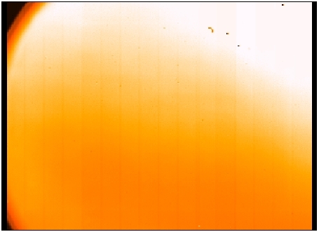
A line cut across the image shows the unusual background produced by the
radiation from PWFS2 seen by Michelle; it is not limited to the regions
indicated in the OT but extends to the middle of the array. The background
in this filter would normally be about 35000 ADU.
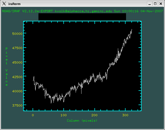
The saturation level for Michelle is about 56000 ADU. This brightness level is reached in the upper right corner of the raw nod images, and line cuts become flat in this region.
When the difference images are taken and are stacked with the
mireduce Gemini/IRAF task the direct evidence of the saturation is
lost. However one can still detect that the upper right corner of the
resulting image has unusual noise properties when one plots the resulting
image with the "zs+" option. This is shown below. (The target of this
observation is too faint to see in this image. One sees only noise across
the frame.)
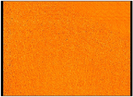
The sign of saturation is the suppression of the pixel to pixel
variations in the frame. One also sees a faint stripe pattern at
an angle of about 45 degrees E of N in the upper right corner.
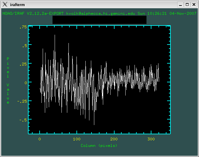
A cut through this region shows the reduction in pixel to pixel fluctuations
in the stacked image where the probe was in the field of view. See the line
cut below, where the pixel to pixel fluctuations are reduced past about pixel
180 in the image.
If a Michelle or T-ReCS observation is taken in cloudy conditions it may be that some of the individual nods saturate due to clouds passing through the field. Such cases are rare, since we normally do not observe with the mid-IR instruments in worse than light CC=70% conditions. However when this happens what is usually seen in the stacked image is a reduction in the dynamic range. One either sees a flattening of the profile across the object or a suppression of the pixel to pixel fluctuations in the resulting image, depending upon the severity of the saturation in the nods. The only way to be certain that nods are not saturated is to examine the individual nods of an observation and remove those that are adversely affected by the clouds.
Last update 2007 November 13; Kevin Volk.