Announcements
Spectroscopy
MAROON-X is high-resolution (R~85,000), optical (500-920nm), fiber-fed echelle spectrograph.
The instrument is designed to have the capability to detect Earth-size planets in the habitable zones of mid- to late-M dwarfs using the radial velocity (RV) method. MAROON-X is highly stabilized, both opto-mechanically (main optical elements in vacuum, the whole spectrograph inside an environmental enclosure with mK temperature stability), and via its fiber feed (octogonal and rectangular fibers, double-scrambler). A stabilized etalon is used to illuminate a calibration fiber to provide a dense comb of emission lines for simultaneous wavelength calibration.
Spectral range and resolution
MAROON-X has no movable parts and only one mode. The main disperser is a R4 echelle with 31.6 gr/mm. A dichroic splits the light into a ‘blue’ (full range: 491-670nm, order 124-92; useful range: 499-663nm, order 122-93) and ‘red’ (649-920nm, order 94-67). Each arm has a VPH grism cross-disperser and camera optics optimized for their respective spectral grasp.The two echellograms are shown below.
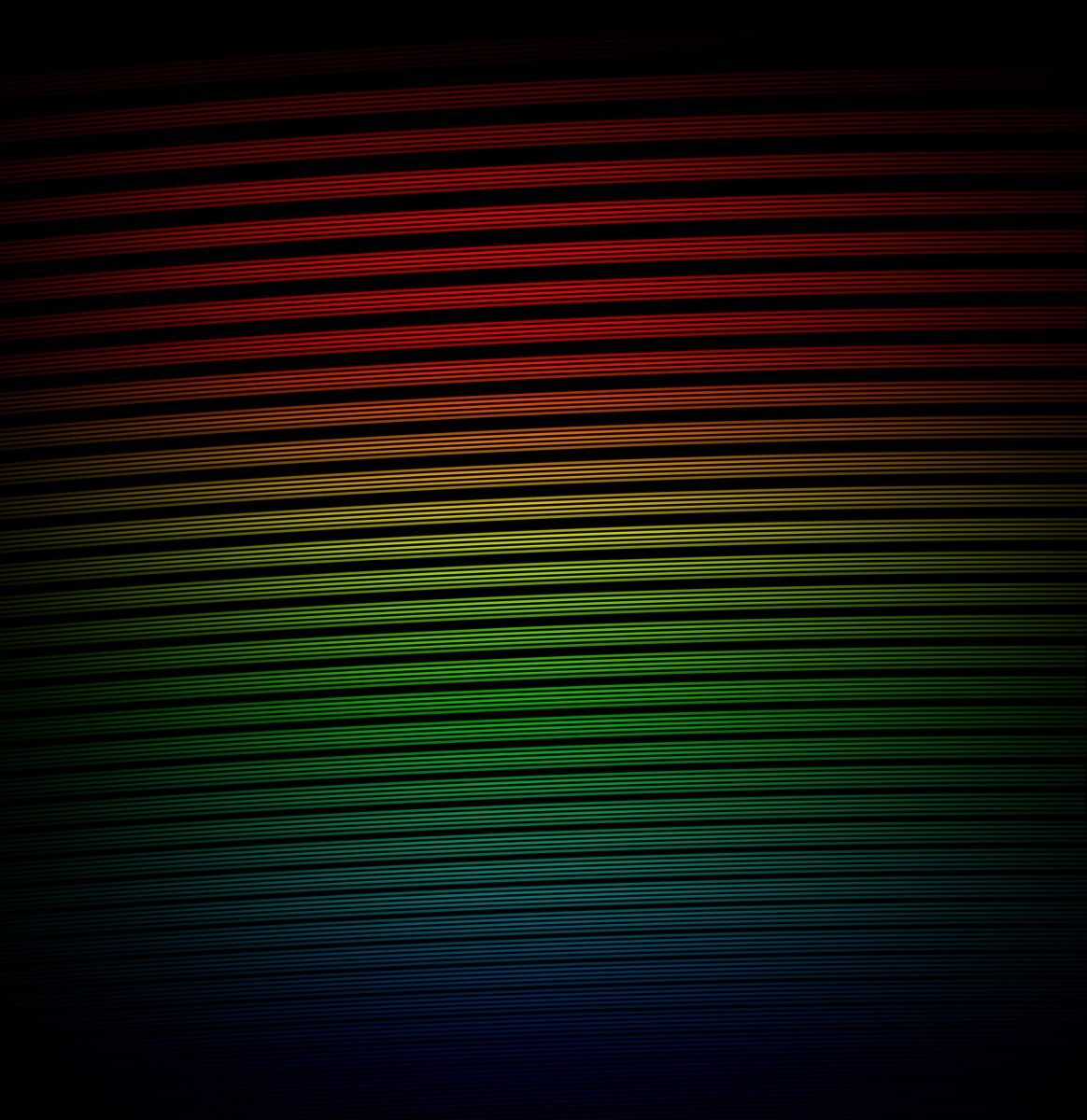

Figure B1. Left: Spectral format of the visual arm of MAROON-X (roughly true color); Right: Spectral format of the NIR arm of MAROON-X (false colors). Increasing wavelengths run from the lower left to the upper right in each image.
The resolving power is typically 80k-88k (see Figure B2), measured as the FWHM of an unresolved line in the extracted 1D spectrum. These measurements were obtained by fitting etalon lines with a combination of a box and an asymmetric gaussian profile. The variability in the resolving power is entirely driven by the field- and color-depended aberrations of the two cameras and by the focus (incl. tip-tilt term) of the CCD detector.
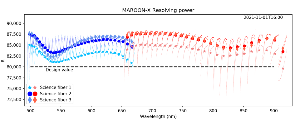
Figure B2. Resolving power of MAROON-X for all three science fibers for the blue and red arm, respectively. The thin traces are points of individually measured etalon line profiles along each order for each fiber. The symbols show the mean resolving power within the FSR of each order.
Slit Format
The spectrograph simultaneously records the spectra of the star, the sky background, and light from a calibration source. The stellar light is sliced three times by a pupil slicer (for details see Components page) and fed into three rectangular fibers. The sky background light is reimaged onto a forth rectangular fiber. Light from a calibration source is injected into a fifth rectangular fiber. These five fibers form the entrance slit of MAROON-X (see image below).
There is sufficient space in between the fibers and in between orders to keep any crosstalk well under 0.1%. Slit tilt and slit curvature are neglectable and the full resolving power is recovered without interpolation along the slit. The flux distribution between the three science fibers is roughly 30%, 42%, 28% of the total flux for fibers 2, 3, and 4 respectively.
Each fiber is sampled by 10 spatial pixels. To enable high-precision RV measurements, each resolution element is sampled on average by 3.2 pixels (varying from about 2.9 to 3.6 pix within the FSR of each order due to the anamorphic magnification of the echelle grating). A resolution element is thus sampled by almost 100 pixels (3 x 10 x 3.2).
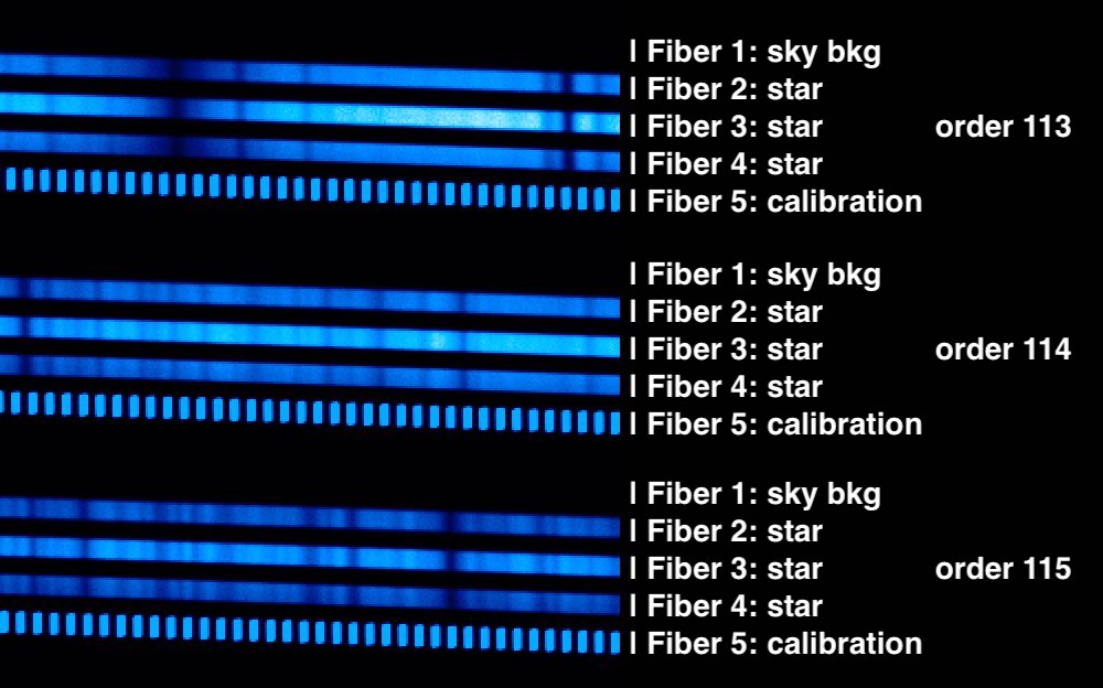
Figure B3. Small cutout from a typical MAROON-X spectrum recorded with the blue arm (around 540nm) to illustrate how the five rectangular fibers are stacked to form a pseudo slit.
Throughput
MAROON-X receives its light from a 100um octagonal fiber, fed at f/3.3. The FOV is thus 0.77” on sky. This is at the order of the IQ75-percentile seeing (0.75”) and makes the throughput of the instrument highly dependent on the seeing conditions. During the commissioning run in December 2019, we encountered different atmospheric conditions with seeing ranging from 0.7” but very unstable (MASS seeing >1”) to better than average (<0.5”) and stable. We have recorded peak efficiencies of up to 11.5% in the red channel for a few observations. However, most of the observations recorded at median conditions (0.4”-0.6” seeing) show a typical peak throughput of 8% in the red and 7% in the blue channel. This is lower than expected based on the instrument throughput measured in the lab and the nominal variability of the fiber coupling efficiency with the image FWHM (e.g., pure geometric losses would suggest 50% coupling efficiency for 0.75” seeing conditions). We are working on isolating the cause of the throughput shortfall and will work on improving the throughput for 2020B.
We thus advise adopting an 8% peak throughput estimate for semester 2020B.
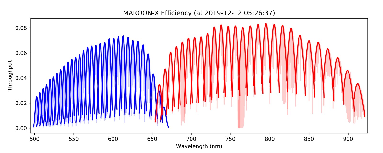
Figure B4. Typical throughput of MAROON-X calculated from observations of a G0V star after airmass correction.
Sensitivity
The sensitivity is canonically expressed as the limiting magnitude to reach a (read-noise limited) signal-to-noise ratio of one per resolution element in a one hour integration. Given the per-pixel read noise (3e-), the number of pixels per 1D spectral bin (3 fibers x 10 pixels each) and the number of 1D pixel bins per resolution element (~3.2 pixels near the blaze peak of each order), we find a limiting magnitude of Ic_limit = 19.5 mag for the peak of the red arm and V_limit = 19.7 mag for the peak of the blue arm.
Instrumental Radial Velocity Precision
MAROON-X follows the instrument concept of high opto-mechanical and illumination stability pioneered by the HARPS instrument. This approach has now been adopted for all recent and future RV spectrographs. However, even the latest generation of highly stabilized spectrographs exhibit drifts exceeding m/s levels on timescales from hours to months due to various practical limitations in the instrumental design and in the environmental control of these instruments. Instrumental drifts need to be monitored and observations corrected accordingly. This requires a calibrator that provides a uniform spectrum with high local information density (many equally bright unresolved emission lines per order) and is long-term stable. MAROON-X is using a stabilized Fabry-Perot etalon illuminated by a white light fiber laser that provides a dense comb of emission lines with a spacing of 15 GHz and an unresolved line-width of 340 MHz. This translates to a line spacing of 2 - 3.6 resolution elements and a completely unresolved line-width of 1/20 to 1/10 of a resolution element between 500 and 920nm, respectively.
Typical exposures taken with the etalon exhibit a photon noise dominated rms of ~5 m/s for the centroid of the individual etalon comb lines (~400 lines per order). The zero point drift of each order can thus be determined to about 25 cm/s. This is more than one order of magnitude lower than the intrinsic RV content per order of a typical stellar spectrum with high SNR. We find no deviations from a smooth wavelength solution at the m/s level confirming the absence of CCD stitching effects.
A second, equally important factor is the illumination stability of the spectrograph, as changes in the illumination of the entrance slit directly translate into measured RV shifts. MAROON-X is using a combination of octagonal and rectangular fibers as well a double scrambler (exchanging near- and far-field) to suppress all spatial information in the light distribution originating from systematic guiding errors at the telescope. This effect is best characterized by observing stars that either show no significant RV signal based on measurements from other instruments, or have well characterized planetary orbits, i.e. so called ‘RV standards’.

Figure B5. Radial velocities for the ‘quiet’ M0V star GJ908 during a 2-week long observing campaign in September 2020. The nightly rms is <30 cm/s. The individual error bars on the datapoints are the error in the mean obtained from 30 spectral orders in the blue arm and 26 spectral orders in the red arm and represent internal errors.
In August 2021 we started observing HD3651, a chromospherically quiet K1V star with a Saturn-mass planet in a highly eccentric orbit (Brewer et al. 2020, AJ, 160, 67B). We find a rms to the orbit fit of 38 cm/s for the red arm and 63 cm/s for the blue arm for two campaigns in August and November 2021.
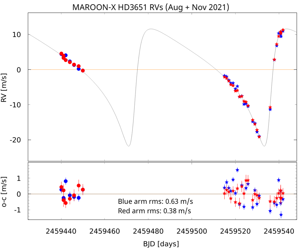
Figure B6. Radial velocities for the HD3651 during a 2-week long observing campaign in August 2021 and a 4-week long campaign in November 2021. The nightly rms to the orbit fit is indicated in the figure.
The results on our RV standards have been achieved without any de-trending against activity indicators like chromatic index, or differential linewidth, and without fitting and subtracting stellar activity signals. The rms values thus represent an upper limit on the instrumental stability as they still contain an unknown level of stellar activity.
It is important to note that while MAROON-X delivers excellent short-term RV precision, long term precision is limited by the intrinsic stability of the etalon calibrator. Before MAROON-X is equipped with a laser-frequency comb, RV data from multiple campaigns spread by a month or more have an additional RV offset with an uncertainty of ~1m/s. This is due to a combination of chromatic drifts in the etalon and the limited chromatic RV information content of the ThAr lamp.
Acquisition and Guiding
MAROON-X has a frontend unit that converts the f/16 beam from the telescope to an f/3.3 beam to feed the 100um (0.77") octagonal science fiber. Primary (i.e. telescope guiding) is using the PWFS2 of Gemini. The frontend unit is mounted on the bottom port of the ISS, a port shared with NIFS and NIRI.
In the frontend unit, the light passes through an atmospheric dispersion compensator (ADC) and a tip-tilt mirror provides flexure compensation between the telescope and the fiber face to provide < 0.1” average centroid stability. To achieve this, ~1% of the light that is sent towards the fiber is picked up by a beam splitter and imaged by a fast and sensitive acquisition and guide camera (sCMOS with >90% peak QE, 400-950nm passband). Three back-illuminated single-mode fibers surrounding the object fiber allow to track the apparent position of the science fiber during the integration. A slow (f<1Hz) guide loop is steering the tip-tilt mirror to keep the centroid of the star on the measured fiber position. Exposure times as short as 0.05s can be chosen. ND Filters allow a further reduction of the flux for bright stars. Exposure times of up to 30sec allow guiding on targets as faint as ~16mag.
A second 100um (0.77") octagonal fiber 20” from the object fiber is used to record the sky background.
The frontend also facilitates the illumination of the object and sky fibers with calibration light. Calibration light (flatfield, ThAr, etalon) is sent up from the spectrograph via an additional fiber integrated into the fiber bundle. The tip-tilt mirror is used to steer the light onto the object or the sky fiber.
Target acquisition: The target can be centered on the fiber in typically less than 1min after the PWFS2 guide loop has been closed by the telescope operator. Depending on seeing conditions, the PWFS2 loop needs to settle for a couple minutes before the exposure begins. If the true target position is off by more than about 5” from its specified position, the PWFS2 guide loop needs to be opened to send larger offsets to the telescope which slows down the acquisition process. The acquisition and guide camera has a vignetting-free FOV of about 60” in diameter and allows to monitor the position of the sky fiber for any contamination by field stars.
ADC: The ADC is designed to provide compensation to better than 50mas from 500-900nm down to airmass 2.5. The ADC can be used in three modes:
- ADC off: no ADC correction.
- ADC fixed: The ADC is pre-set for the average airmass of the observation and kept static.
- ADC tracking: The ADC updates during the observation to compensate for the actual airmass.
In all three modes, the telescope de-rotator can either be fixed (Alt-Az mode) or following (RA-DEC mode). Since the object fiber is on the nominal optical axis of the field, field rotation has no direct impact on the fiber coupling. A fixed telescope de-rotator offers potentially improved image quality through more stable aberration compensation of the telescope. The added advantage is that the parallactic angle is constant and the ADC does not have to follow the de-roator. The only downside is that in a crowded field, background stars might rotate over the sky background fiber and contaminate the sky background spectrum. However, we strongly advise to keep the telescope de-rotator fixed whenever possible.
Guider images: Guider images can be saved if the user requests this option.