Announcements
IFU Spectroscopy
Top-level characteristics of NIFS
The table below gives only a quick-reference overview of the NIFS instrumental parameters. Please consult the relevant subsections for more details.
| Spatial Properties | ||||
| Field of View | 3" × 3" | |||
| Pixel Scale | 0.103" across slices 0.04" along slices |
|||
| Spatial Resolution (FWHM) | 0.1" full AO correction (NGS/LGS) Seeing limited without AO |
|||
| Spectral Properties | ||||
| Grating | Z | J | H | K |
| Standard Wavelength Range (μm) | 0.94 - 1.15 | 1.15 - 1.33 | 1.49 - 1.80 | 1.99 - 2.40 |
| Spectral Resolution | 4990 | 6040 | 5290 | 5290 |
| Guiding Properties | ||||
| Guide Probe | PWFS2 | OIWFS | ALTAIR (NGS) | ALTAIR (LGS) |
| Patrol Field | 3.5 to 6.5 arcminutes | 12.7" to 60" (30" max recommended with ALTAIR field lens) | < 25" | < 25" |
| Limiting Magnitude of A0 Guide Star (minimal performance) | Rmag=15 | Kmag=14.5 | Rmag=15 | Rmag=18.5 |
Basic Characteristics of NIFS Coronagraphic Mode
R~5000 infrared IFU spectroscopy at AO resolutions using the 0."2 or 0."5 occulting disks for coronagraphic measurements is available. The best performance is achieved in the H and K bands. Coronagraphy can be carried out with or without ALTAIR's field lens, and with or without a NIFS OIWFS guide star.
Spatial Sampling and Image Quality
Introduction
NIFS is an image-slicer integral-field spectrograph, meaning that the sky is sampled by a stack of long, thin mirrors, each of which is rotated with respect to its neighbors. Each of these narrow mirrors acts similarly to a slit in a conventional spectrograph, providing a slice across the two-dimensional field that is then dispersed to provide a spatially-resolved spectrum. Since there are almost no gaps between the slices (or 'pseudo-slits'), they can be re-combined to provide a contiguous field, in which there exists a spectrum at every position.
Field of View
During science verification, the NIFS field of view was measure as 2.99"×2.97", measured across and along the slices respectively The field is divided into 29 individual slices, each of which is sampled by around 69 detector pixels running along the length of the slice. Distortions within the NIFS field are very small. The orientation of the NIFS field is such that the slices are aligned North-South for an instrument position angle of 0º.
Spatial Sampling
A consequence of the image-slicer design is that the spatial sampling is determined differently across the slices than along them. In the direction along the slices, the sampling is determined by the detector. Across the slices, the sampling is determined by the width of the slice as projected onto the sky. For NIFS, this results in rectangular spatial pixels (or 'spaxels') of dimension 0.103"×0.043" across and along the slice respectively.
Image Quality
The image quality of NIFS is determined primarily by the guiding method. Without the use of the ALTAIR adaptive optics system, NIFS is seeing limited, which is typically 0.4" FWHM or larger. If ALTAIR is providing full correction, using a bright NGS or LGS with a bright tip-tilt star, the PSF is close to the diffraction limit of the telescope, which is undersampled by the NIFS 0.1" slices. Thus along the slit, the PSF will be well sampled and near-diffraction limited. Across the slit, the PSF will be affected by the sampling of the NIFS slits. NIFS image quality with AO can be affected by a number of issues that are generally not important for seeing-limited observations. For example, flexure or changes in atmospheric refraction during the integration, the quality of the image-reconstruction via the data reduction process, etc. Nominal FWHM values for NIFS+ALTAIR observations with good correction are 0.1"-0.15", although precise PSF size and shape will depend on conditions and ALTAIR configuration.
Sensitivity
The following sensitivity table provides signal-to-noise ratios (S/N) of 5 per spectral pixel in one hour (6 x 600 seconds) on-source integration. They were estimated using the NIFS Integration Time Calculator (ITC) and the obtained S/N of 5 is the averaged S/N in the wavelength intervals. These values are for silver coatings on the telescope optics and NIFS on the up-looking port, and the lowest-read noise mode was assumed (~6 e- at 77 K). Observing conditions were 70%-ile image quality, 50%-ile cloud cover (photometric), 80%-ile water vapor column, 80%-ile sky background, and an average airmass of 1.5.
Although these ITC estimates are not far off the actual NIFS measurements, detailed calculations show some inconsistencies. Thus, these estimates are provided only for proposal preparation and are not meant to be absolute guides. Nonetheless, applicants should use the ITC to estimate the signal-to-noise ratio at the precise wavelengths of interest and/or over the entire band of interest.
| Band | Wavelength Interval (um) | Central Wavelength (um) |
Point Sources | Extended Sources | ||
| (mag) | (uJy) | (mag/IFU pixel) | (mJy/IFU pixel) | |||
| Z | 0.94 - 1.15 | 1.05 | 16.0 | 870 | 14.7 | 2.9 |
| J | 1.15 - 1.33 | 1.25 | 16.8 | 340 | 15.5 | 1.1 |
| H | 1.49 - 1.78 | 1.65 | 18.3 | 55 | 17.0 | 0.2 |
| K | 2.00 - 2.41 | 2.20 | 18.7 | 26 | 17.4 | 0.1 |
Performance Monitoring
NIFS Sensitivity
The sensitivities reported for NIFS reflect the magnitude of an object that would provide a signal-to-noise ratio of 1 for an hour of integration time (SN1 hr). To calculate the signal-to-noise ratio, the signal is determined from telluric standard stars observed with requested photometric (CC50) IQ20 to IQ70 conditions, while the noise is determined from a subtracted pair of long-sky frames. The sky frames used have an integration time (T) > 500 seconds, observed within temporal proximity of the telluric standard, and are observed under the same photometric conditions.
The signal is found by taking the mean over the telluric's spectrum (S) with a circular aperture area defined by the guiding source. For AO and P2 guiding, apertures are fixed at 0.3'' and 2.5'', respectively.
With a subtracted pair of long-sky frames, on an area of sky generally free of sky lines and artifacts, noise (N) is determined by multiplying the average standard deviation in the background counts by the square root of the aperture area used to find the signal.
| SN1 hr = | S * (3600 / Ttelluric)
N * (3600 / (2 * Tsky))1/2 |
To find the sensitivity, the signal-to-noise ratio (SN1 hr) is converted to a magnitude and added to the Simbad magnitude (MSimbad), in the corresponding waveband, of the standard star:
| Sensitivity = 2.5 * log(SN1 hr) + MSimbad . |
Sensitivity measurements for telluric standard star observations, taken at the central wavelength of each band, are reported below. The Gemini Integration Time Calculator (ITC) predictions for IQ20 and IQ70 (CC50) conditions are drawn in the sensitivity plots. For NIFS-P2 the ITC calculations do not differ for IQ20 and IQ70 conditions, and only one dashed line is shown. The NIFS-AO predicted sensitivities do exhibit noticeable differences between IQ20 and IQ70 conditions. For NIFS-AO observations, measurements made with the field lens OUT are represented by a larger symbol than those made with the field lens IN, as the field lens will contribute to signal being lost.
| NIFS Sensitivity | AO Guiding | P2 Guiding |
| Plots | NIFS-AO | NIFS-P2 |
Throughput
All throughput measurements are based on observations of spectrophotometric standards, collected under photometric conditions. Throughputs are defined as follows:
| T(λ) = | Nd(λ)
Nt (λ) |
where: Nd(λ) is the number of photons detected with wavelength λ and Nt(λ) is the number of photons of the same wavelength hitting the telescope's primary mirror. The latter is given by:
| Nt(λ) = N*(λ) 10 (-0.4 μ Aλ) |
where N*(λ) is the star's photon flux at wavelength λ above Earth's atmosphere, in number of photons/cm2/s, μ is the airmass, and Aλ is a mean monochromatic extinction coefficient.
The numbers available below are average values, that do not account for throughput variations as a function of grating angle.
Guiding Options
NIFS has a number of different guiding options, which can be summarized as follows:
- Without Adaptive Optics: Seeing-limited guiding using Peripheral WaveFront Sensor 2 (PWFS2). This mode can be used if there is no suitable guide star available for ALTAIR (e.g., no nearby bright star and your target is too faint or extended to guide with).
- With Adaptive Optics: ALTAIR is used as the primary guider, providing adaptive optics correction for seeing effects. ALTAIR provides both Natural Guide Source (NGS) and Laser Guide Source (LGS) capabilities with NIFS, and can be used as a "seeing improver" using PWFS1. The degree of correction depends on the brightness and off-axis distance of the guide sources used. Note that the Altair patrol field is not exactly circular or concentric with NIFS. The precise position and non-circular shape of the patrol field is correctly displayed with the Altair overlay in the Observing Tool image displayer.
- With Adaptive Optics and OIWFS: NIFS is also equipped with an On-Instrument WaveFront Sensor (OIWFS) that can provide slow guiding to correct for flexures between NIFS and ALTAIR. This mode is recommended for long integrations, and for coronography.
Guidelines for selecting good guide stars are summarized in the table below. Note that the guide star brightness limits are for cloudless nights (50% CC) andoptimal seeing (IQ ≤ 70%). ALTAIR can guide on fainterstars (to R~15 mag for A0 stars), but this will result in poor correction.
| Guide Probe | Separation from the science target |
Guide star brightness |
| ALTAIR (NGS) | < 25" (1) |
R <~12 mag (optimal) R <~15 mag (faint limit) |
| ALTAIR (LGS) | < 25" (1) |
R <~17.5 mag (bright time) R <~18.5 mag (dark time) |
| LGS+PWFS1 | 3.5' to 7' | R <~ 14 mag |
| OIWFS | Between 12 and 60" (2) | K <~ 14.5 mag |
| PWFS2 | 3.5' to 6.'5 | R <~ 15 mag |
(1) The Altair patrol field is not exactly circular or concentric with NIFS. The precise position and non-circular shape of the patrol field is correctly displayed with the Altair overlay in the Observing Tool image displayer.
(2) The maximum radius decreases to 25" when the ALTAIR field lens is used.
Seeing limited NIFS IFU spectroscopy
In addition to the adaptive optics-fed mode, NIFS has also been commissioned to be used with the Peripheral Wavefront Sensor, PWFS2. The NIFS field will be vignetted by the PWFS2 probe arm using stars that are closer to the science target than ~3.8 arcminutes. The outer limit for PWFS2 guide stars can be displayed on the OT position editor and is discussed here. More information on the Peripheral Wavefront Sensor vignetting regions and information on how to define PWFS2 guide stars can be found in the OT help pages .
Extensive flexure modeling of the NIFS+PWFS2 system has not been done, but we presume that guiding with NIFS in this mode will provide performance similar to the NIRI+PWFS2 observations (roughly 0.1" of flexure per 30-45 minutes of on-sky observations, depending on the elevation and rotator position). It is not presently possible to use the NIFS OIWFS guide stars to compensate for flexure when observing with PWFS2.
Required Guide Star Characteristics: See the table on the main guiding options page for limiting guide star magnitudes for PWFS2.
With AO
Observations made with NIFS+ALTAIR adaptive optics are the most common observing mode. Typically, the adaptive optics correction with ALTAIR on a bright star gives a best-fit FWHM value of 90 - 110 mas. The FWHM is limited by the rectangular 0."1 x 0."04 pixels in the NIFS spectrograph, so the ALTAIR PSF is sub-sampled by the NIFS spectral pixels. We found that guiding with NIFS+ALTAIR yields correction results that are largely consistent with the performance described on the ALTAIR pages, resulting in image quality of around 0.1-0.15" FWHM.
An upgrade to the ALTAIR adaptive optics system during late 2005 made available a Field Lens for ALTAIR AO observations. The field lens allows ALTAIR to deliver a higher and more uniform Strehl ratio across a larger field of view, and consequently improves the correction from ALTAIR in the NIFS field when guiding off-axis. The field lens MUST be used for NIFS+ALTAIR observations with the Laser Guide Star. For ALTAIR NGS, the field lens is recommended when the guide source is more than 5" off axis. More information concerning the field lens can be found on the ALTAIR field lens web-page.
Required ALTAIR Guide Star Characteristics: See the above table on this section for useful guide star separations and brightnesses for ALTAIR guide sources. See the ALTAIR pages for more detailed information on the guide performance vs. stellar magnitude for wavefront sensor stars. Also, the NIFS OT Details page has information on guide fields of view and configurations for NIFS+ALTAIR stars.
With AO and OIWFS
ANNOUNCEMENT: January 2013 - OIWFS is not currently available due to a faulty sensor.
Introduction
For each new instrument that is used with ALTAIR, an extensive model is generated at a range of elevations and rotator angles to remove the flexure between the Telescope-ALTAIR-Instrument system. While this model is very good at removing the vast majority of the system flexure, it is not perfect. The accuracy of the flexure compensation depends upon the deviation of the model from the true flexure for a given elevation and position of the rotator. Hence, some elevations/rotator positions have very accurate flexure compensation, while others deviate from the model. The typical flexure residuals for the NIFS+ALTAIR flexure model are small, ~0."10 to 0."15 RMS. However, when observing for long exposure sets for NIFS frames it is desirable to remove as much of the residual flexure as possible.
The NIFS instrument is equipped with an infrared On-Instrument Wavefront Sensor (OIWFS), which has the following technical properties:
- Wavelength range: 0.95-2.5 microns (Z through K-band spectroscopy)
- 2" diameter FOV
- Steerable over 180" diameter field centered on NIFS
- Image scale: 0."17/pixel
- Filters: J, H & K
- Detector: 1024x1024 HgCdTe HAWAII detector
Purpose of the OIWFS
Historically, the infrared OIWFSs were supposed to provide fast tip/tilt guiding in sky regions that did nothave a suitable optical wavefront sensor star for PWFS1 or PWFS2.However, unlike these scenarios for the NIRI and GNIRS OIWFSs, the NIFS OIWFS has been commissioned to be used solely in conjunction with ALTAIR adaptive optics and will only be used to provide slow flexure corrections.
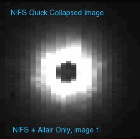
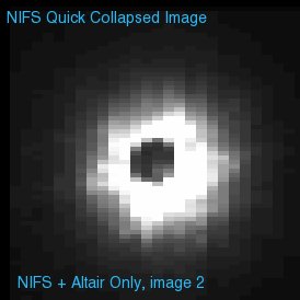
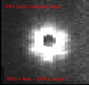
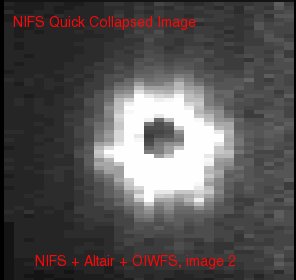
The NIFS OIWFS can be used to remove as much of the residual 0.10-0.15"/hour from the NIFS+ALTAIR flexure model as possible. This allows for longer on-source observations of a science target with little residual flexure movement of the object. The performance of the NIFS+ALTAIR+OIWFS system has proven to be especially useful when taking observations with a bright star centered behind an occulting disk (seebelow figures). This mode may also help with precise re-centering of the science field following telescope motions (e.g. after a large offset and when a focal plane mask is being used).
When to use the OIWFS
Faint objects: If possible, the OIWFS should be used for long exposures (>∼300sec), to avoid smearing of the image by flexure during the integration. In particular, the OIWFS may be most useful for deep integrations where the science target or a reference source is not visible in a single exposure. By using the OIWFS, you can be more certain that the (invisible) target has remained in the same position in the NIFS field (modulo pointing offsets or dither patterns) during an observation sequence. This can be useful to allow accurate co-adding of exposures using the offset information directly, since you do not have a reliable reference source in each individual exposure.
Coronography: In this case, the OIWFS is critical to maintain the absolute position of the object in the NIFS field, behind the occulting disk. Note, however, that the OIWFS star cannot be on-axis.
|
The benefits of using an OIWFS star - less flexure movement of target |
|
 |
 |
| ALTAIR Only: NIFS + ALTAIR Observation with the 0."5 occulting disk, first image after acquisition is shown on the left. NIFS + ALTAIR Occulting Disk Observation, image 2 (on right) taken 30 minutes later, showing ~60mas of flexure movement since the beginning of the observation set. | |
 |
 |
| ALTAIR+OIWFS: NIFS + ALTAIR + OIWFS Observation with the 0."5 occulting disk, first image after acquisition is shown on the left. On the right, an image taken 30 minutes later is shown. The ALTAIR+OIWFS guide configuration has resulted in very little flexure of the star behind the occulting disk during the observation set. | |
Accessible Field of View for OIWFS
The OIWFS is physically located below the NIFS pick-off arm, which vignettes a 25.4 arcsecond diameter circular region around the NIFS field centre, as well as a rectangular strip of 25.4 arcsecond width extending to the edge of the OIWFS field. This vignetted region is displayed as a red 'horseshoe' in the OT display tool. The vignetted region lies within the outer edge of this horseshoe.
When using ALTAIR without the field lens: In this case, the effective field of view of the OIWFS is limited to a 60" radius around the NIFS field centre. Due to the nature of the AO correction, stars will be elongated within the accessible field of the OIWFS, which may affect the OIWFS performance. For best flexure correction with OIWFS, it is recommended to use the field lens if a suitable guide source exists.
When using ALTAIR with the field lens: The ALTAIR field lens only corrects within an approximately 30" radius of the NIFS field. Furthermore, there is a vignetted region just outside this 30" limit due to the field lens mounting, but this vignetting is not well characterized, and is not represented in the OT overlays. OIWFS stars used outside the field lens limit will be elongated, and will not provide useful corrections. Therefore, when using the field lens, you must select an OIWFS star that is inside the 30" field lens limit.
Required Guide Star Characteristics: See the above table on this section for useful guide star separations and brightnesses for ALTAIR and the NIFS OIWFS. Note that the performance of the OIWFS also degrades as the distance between the OIWFS and AO guide sources increases, due to anisoplanatism.