Instrument Support Structure
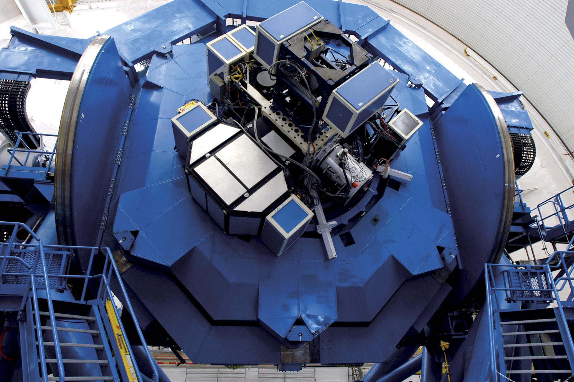
Instruments are mounted at the Cassegrain focus on the instrument support structure (ISS). The ISS is a stiff cube that itself houses the Acquisition and Guidance Unit which contains the Acquisition Camera and Peripheral Wavefront Sensors (guiders). A science fold mirror mounted inside the ISS can be rotated to send the light from the telescope to any of four side-looking ports, or can be retracted so that the light goes to the up-looking port.
The ISS is attached to the telescope via the Cassegrain rotator, which may be oriented at any desired position angle and which normally rotates during observations to compensate for rotation of the field of the alt-az telescope.
The instrument specifications webpage provides detailed information relevant to ISS-mounted instruments including interfaces and environmental conditions.
It is useful to understand the ISS position in relation to the telescope when parked at Zenith (it is underneath), and the telescope position on the observing floor, and mount.
Optics
Telescope Optical Configuration: Ritchey-Chretien Cassegrain.
Telescope Prescriptions: GN Zemax model | GS Zemax model (GN=MK/Mauna Kea and GS=CP/Cerro Pachon).
Primary Mirrors: Each mirror is an f/1.8, 8.1 m diameter, 20 cm thick meniscus, and weighs 22,200 kg. Each was made from 55 blocks of low expansion (ULE-581) glass fused together at 1700 degrees C and slumped at Corning's Canton, New York facility. Each mirror blank was then shipped to REOSC Optique in Paris, France, for polishing of its reflecting surface to that of a concave hyperboloid. The measured surface accuracy is 15.6 nm (rms).
Secondary Mirrors: Each secondary mirror is 1.0 m in diameter. Each was prefabricated by Schott from Zerodur and then polished by Zeiss to a convex hyperbolic shape and lightweighted by 85%. The weight of each secondary is 54 kg. The rms surface accuracies are 17 nm for the Gemini N mirror and 13 nm for the Gemini S mirror. Each secondary mirror is mounted on a rapid tip-tilt and chopping mechanism designed and built by Lockheed. Tip-tilt correction is possible up to 200 Hz. The chopping capabilities are: any position angle on the sky at frequencies up to 3 Hz; amplitudes up to 15 arcsec on the sky; and a duty cycle of 87% at the above values.
Science Fold Mirrors: These are plane mirrors at 45 degrees that reflect the converging beam near the Cassegrain focus of each telescope to an instrument mounted on one of four side-looking ports of the Instrument Support Structure (ISS) or may be retracted to allow the beam to reach the up-looking instrument on the bottom port of the ISS.
Effective Focal Lengths of Telescopes at Cassegrain Focus: 128.12 m (f/16).
Plate Scale at Cassegrain: 1.610 arcsec/mm.
Field of View at Instrument Focal Plane: Maximum 10 arcmin diameter on the bottom port, and 7 arcmin diameter on the side ports due to science fold mirror size. Limiting factors on FOV are the diameter of the central openings of the WFS mounting rings in the WFS, the portholes in the ISS, and the Science Fold Mirror diameter. PWFS can also vignette the beam - the PWFS can reach an outer radius = 7 arcmin before one edge of their field starts to be vignetted (the 14 arcmin diameter is slightly larger than the instrument FOV because the PWFS are upstream of the Science Fold and ISS ports).
Mirror Coatings: For optimal infrared and visual performance and durability, the primary and secondary mirrors and the science fold mirrors now have protected silver coatings. Mirrors are recoated every 3-5 years to maintain performance. This compilation of reflectivity data (link will download xls file) describes coating performance across a broad range of wavelengths and over time.
Throughput: Throughput may be calculated as the product of the reflectivities of the Primary, Secondary and Science Fold mirrors. The bottom port does not use the Science Fold mirror but Gemini cannot guarantee instrument port assignment.
Baffles: Gemini has permanently installed baffles that are deployable with two positions - IR and Optical. They do not allow use of the full 7.5 arcmin field without vignetting. The Optical mode (extended) works at 12.0 arcmin, with extended diameter 2003mm. The IR mode (retracted) works at 3.5 arcmin with retracted diameter 1124.6mm. There is also a sky periscope at the center of the secondary mirror for IR instruments to see sky rather than the primary's central obstruction. This periscope is shuttered for optical instruments.
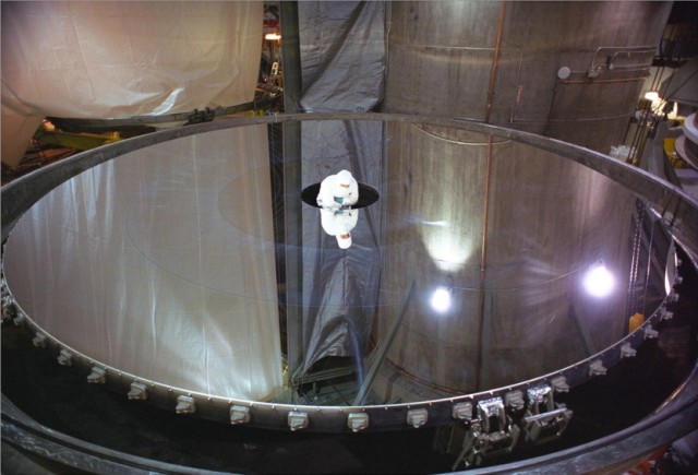
Primary mirror during inspection at Gemini North
|

Gemini North's 1.0 m secondary mirror
|
Silver vs. Aluminum
Below are reflectance plots for coatings of bare aluminum (Al), bare silver (Ag), and silver with various protective layers. Gemini uses the 4-layer coating on all three telescope mirrors (primary, secondary, and science fold). The emissivity, E, of these coatings is related to the reflectance, R, by the equation E=1-R.
Protected silver has higher reflectance than aluminum at all wavelengths longer than ~450nm. Throughout the thermal infrared, where emission is an important source of contaminating background radiation, protected silver, which has emissivity of a little over 1%, offers a 2-3 times reduction in emissivity over aluminum. Below 450nm silver is inferior to aluminum; its reflectance drops to zero near 310nm.
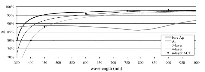
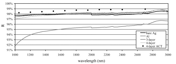
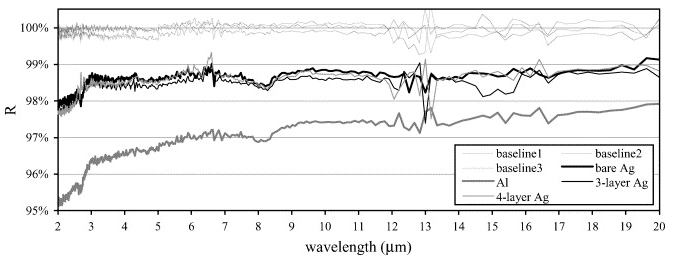
The plots are from Boccas et al. 2006, Thin Solid Films, 502, 275
Acquisition Hardware and Techniques
Dedicated to the Acquisition and Guidance Unit (A&G), this section includes descriptions of the instruments on Gemini that are used to acquire the science target after the telescope has been slewed to the approximate coordinate of the target. It also describes the commonly used methods for accurate placement of the target with respect to the field of view of the science instrument.
Acquisition and Guidance Unit
The Acquisition & Guiding (A & G) unit is located within the instrument support structure (ISS), which is mounted on the cassegrain rotator (CR) of each telescope. The CR may be rotated to any desired position angle. Because the telescopes are alt-az mounts, the CR normally moves during an observation to de-rotate the field.
Limitations
To understand the limitations on use of the peripheral wavefront sensors (PWFSs) and Acquisition Camera, and how the telescope beam is redirected to the instruments or from the facility calibration unit, GCAL, it is useful to visualise the nested modules of the A & G system.
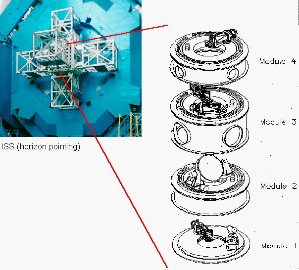
The A & G module contents
- Module 1: acquisition camera/high resolution wavefront sensor.
- Module 2: science fold, directs telescope beam to a side-looking science instrument or retracts to allow passage of beam to the up-looking instrument. Alternatively can feed AO-corrected beam or calibration unit to science instruments.
- Module 3: second peripheral wavefront sensor and facility AO pick-off mirror.
- Module 4: (closest to the sky) first peripheral wavefront sensor.
Modules 2, 3 and 4 may rotate independently about the vertical axis.
Acquisition Cameras
The Acquisition Cameras are optical CCD-based instruments within the Acquisition and Guidance (A&G) unit (module 1). Each Acquisition Camera provides two major capabilities:
(1) telescope pointing verification via short exposures and fast readout of bright stars; and
(2) target selection via intermediate-length exposures.
Retraction of the science fold mirror (used to direct the telescope, calibration or AO-corrected beam to a side-looking instrument), and insertion of the Acquisition Camera pick-off mirror allows a visible-wavelength image of the field to be taken.
The Acquisition Camera can double as a high-resolution wavefront sensor (HRWFS) to measure the shape of the primary mirror), by insertion of a lenslet array in front of the detector.
Each Acquisition Camera has two filter wheels, one with bandwidth-limiting color filters and the other with neutral density filters. The detectors are TE-cooled, frame-transfer CCDs with 1Kx1K pixels covering a 2x2 arcmin2 field of view. There is no shutter.
The individual pixel size is 0.12 arcsec. The minimum exposure time is 0.006 seconds and the full frame readout time is 1.7 seconds.
The Acquisition Cameras have been offered for science use in the past. For completeness, the old Acquisition Camera pages are still available, although the site is no longer maintained.
Gemini International Observatory thanks the German Aerospace Center (DLR) and the Deutsches SOFIA Institut (DSI) / Institute of Space Systems (IRS) at Universität Stuttgart for donating spare CCD47-20s that were originally intended for instrumentation for the Stratospheric Observatory for Infrared Astronomy (SOFIA). These detectors will ensure continued operation of the Acquisition Camera / HRWFS for the foreseeable future.
Acquisition Techniques
Acquisition refers to the accurate placement of the target(s) in the field of view of a camera or the slit(s) or Integral Field Unit (IFU) of a spectrograph. The Gemini spectrographs often are designed with the option of very narrow slits to take advantage of the high quality images delivered by the telescope. The positioning of targets in such narrow slits requires care. The basic procedures outlined below will provide the best slit centering possible given current telescope offsetting performance.
Targets Visible in the Instrument's Imaging Mode
The best slit centering is achieved when the target can be detected in modest (<1 min) acquisition images. The centering is fine-tuned by the observer and will be better than 10% of the slit width.
Blind Offset Acquisitions
When centering on the actual target is not possible, a reference star at an accurately known reference position is used instead. The telescope is slewed to the science target first, and guiding is started. The telescope is then 'offset' to the reference object, which is used for fine-tuning the slit centering. The offsets are then removed to return the telescope to the position of the science target.
The accuracy of such offsets decreases with increasing distance to the reference star, so it is important to choose the nearest reference star possible. The current offset accuracy is approximately 0.2 arcsec for a reference star 50 arcsec from the science target.
The Phase II Science Program must contain clear instructions on what the offsets are to the reference object. The preferred way of specifying offsets to the reference object is to include accurate coordinates for the reference object stored as a "Blind-offset (1)" target (i.e. Type Tag = Blind-offset (1) in the Target Environment). The "Base" target is the science target. It is essential that the coordinates of the reference star be accurate and be in the same reference frame as the coordinates of the science target so that the telescope control system will determine accurate offsets between the two positions. Both coordinates must be specified in J2000.
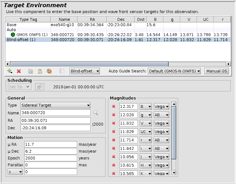
It is important that the relative offsets between the reference star and the faint target be very accurate. These offsets are best determined by measuring the positions of both objects on the same image with good relative astrometry. If the science target, reference star, or the guide star have proper motions, then these should be entered in the Motion section of each target.
No matter what method is used to specify reference object offsets, the wavefront sensor used for guiding must remain active during the offsets to the reference star. It is important to check that the guide star is accessible for both the science target and the reference star.
Offsetting to a reference object may also be helpful for brighter targets when the science target identification might be confused, as in crowded or complex fields. Additional information about complicated setups should be included in a Note in the OT.
Mid-infrared observations also require an additional "hot-spot" star, as detailed on the mid-IR astrometry web page.
Multi-object Spectroscopy Acquisition
See the GMOS target acquisition information.
Guiding and Wavefront Sensors
Essentially all observations with the Gemini telescopes require the use of either a peripheral wavefront sensor (PWFS) or an on-instrument wavefront sensor (OIWFS) assigned to a star near the science target, and in some cases an adaptive optics wavefront sensor (AOWFS) assigned to a star or artificial laser guide star, in order to:
(1) remove low order aberrations of the primary mirror;
(2) compensate for image motion due to telescope tracking inaccuracies, wind-shake, and atmospheric effects; and
(3) for some near-infrared observations to correct for blurring of images by the earth's atmosphere.
These enhancements to the image quality are achieved respectively by:
(1) manipulation of the primary mirror figure (adaptive optics, AO) on one-minute timescales;
(2) articulation of the secondary mirror typically on ten millisecond timescales; and
(3) adjustments to the shape of a small deformable mirror on millisecond timescales (adaptive optics, AO).
When adaptive optics is not in use the PWFSs are employed by instruments that do not have their own built-in WFSs. Instruments with built-in WFSs usually do not use the PWFSs, although a PWFS may be used.
The region of sky in which a suitable guide star must be found for the WFS is limited to an small area close to the science target. In almost all, but not all cases a suitable star can be found; see this page for some indication of likely guide star availability.
The wavefront sensors may be configured in various ways.
- For most observations without adaptive optics, one PWFS or the OIWFS is selected for use. The estimates of delivered image quality assume normal operation.
- At Gemini North, for normal natural guide star adaptive optics, ALTAIR itself provides the tip/tilt and focus correction (using either the optical light from target itself or that from a very nearby point like object).
- For laser guide star adaptive optics (at Gemini North) normally a very nearby tip/tilt and focus star is used with ALTAIR. If a nearby star is not available PWFS1 can be used to improve the natural seeing FWHM by a factor of 2-3; see here for further information.
Peripheral WFS (PWFS)
Two peripheral wavefront sensors (PWFS1 and PWFS2) are part of the Acquisition and Guidance (A&G) system located within the instrument support structure (ISS) cube. Both PWFS1 and PWFS2 perform primary mirror active optics control in addition to directing the tip/tilt secondary mirror.
- At Gemini North PWFS1 consists of a 2x2 lenslet array feeding 2D array detector and PWFS2 has a 2x2 lenslet array feeding its array detector.
- At Gemini South PWFS1 consists of a 6x6 lenslet array feeding 2D array detector and PWFS2 has a 2x2 lenslet array feeding its array detector.
A selection of filters covering the optical and near-infrared (e.g., V,R,I) is available for each array. Mounted on rotary stages, and as their name implies, the PWFSs patrol an annulus of sky around the science field. The PWFSs are upstream of the science instruments and, although they can be moved into the center of the field for engineering purposes, they will vignette the science field unless positioned at sufficient distance from field center.
The minimum angular distance (i.e. inner patrol radius) of the PWFS1 and PWFS2 stars from the field center differs for various instruments and their configurations. For example, the PWFS2 guide star must be at least the following distance off-axis to avoid vignetting the science field: NIRI imaging f/32 camera - ~4.2 arcmin; f/14 camera - ~4.6 arcmin; f/6 camera - ~5.0 arcmin; NIRI spectroscopy - depends on slit width and orientation, but can be as small as ~4.0 arcmin; check the individual instrument pages for more details. For PWFS1 the minimum distances are typically 0.5' larger than for PWFS2; Acquisition Camera - ~6.1 arcmin.
The outer patrol radius depends on the location of the star in the patrol field and the amount of motion needed for focus corrections. Guide stars should be within 6.9 arcmin of the science target if possible, although separations of up to 7.0 arcmin are useable in some circumstances. The available patrol annulus thus is the region between the relevant inner radius and the 6.9 arcmin outer radius. PIs are urged to use the Position Editor feature of the Observing Tool for an accurate view of the focal plane, instrument field of view and vignetting, when setting up their observations to be sure that the WFS does not vignette their field of view. Please also be sure to check that any offsets in the sequence that are intended to be guided do not cause the guide star to fall outside the usable range.
Approximate limiting magnitudes for effective use of PWFS1 and PWFS2 are given in the following table.
| R MAGNITUDE LIMITS OF PERIPHERAL WAVEFRONT SENSORSa |
||
| Telescope | PWFS1 | PWFS2 |
| Gemini North | 14 | 14 |
| Gemini South | 12b | 14 |
(a) For clear skies, good seeing, partial moon (CC50, IQ70, SB80), and tip/tilt running at 200 Hz. Limits are worse for worse seeing, clouds, more moonlight. Limits are one magnitude fainter if tip/tilt is run at 50 Hz. When chopping, the limits are roughly one magnitude brighter.
(b) At Gemini South, because of its larger number of lenslets, PWFS1 is capable of making more accurate measurements of the primary figure. However, the larger number of lenslets means that it must observe brighter stars than PWFS2.
In general it is recommended that one use PWFS2 rather than PWFS1 and that one select the brightest PWFS star within the usable annulus that is fainter than ~7th magnitude.
Guide stars are usually acquired using a red filter, so magnitudes as close as possible to R band are most relevant (other filters can be used if, for example, the only available guide star is very blue; in cases like this please alert your NGO/contact scientist at Phase II). Note that the simple PIT search (required for phase I proposals) usually selects the brightest guide star available, but it may not be bright enough for the WFS. The delivered image quality degrades very rapidly for fainter stars. Guide stars must also be real, single, point sources as opposed to galaxies, double stars or diffraction spikes around bright stars, for example; some guide star catalogues contain many such objects.
On-Instrument WFS (OIWFS)
Some of the Gemini facility instruments have on-instrument wavefront sensors. For the optical instruments (e.g. GMOS) the OIWFS is a CCD. For the near-IR instrument NIFS the OIWFS is itself a near-IR detector. NIRI, Phoenix, TEXES, and most other visiting instruments have no OIWFSs and use the PWFSs.
As they are located very much closer to the instrument focal plane than the PWFS, the OIWFS have a much smaller vignetting footprint, albeit with a more limited patrol field. The optical OIWFSs have higher sensitivity than the PWFSs, which compensates for their smaller patrol fields. See the specific instrument pages for availability of each OIWFS and details of patrol field restrictions and sensitivity.
Adaptive Optics WFS (AOWFS)
ALTAIR, the adaptive optics system of the Gemini North telescope, can be used with either a bright natural guide star or a laser guide star. When the laser is used a nearby natural guide star is also required for tip/tilt and focus corrections.
GeMS, the multi-conjugate adaptive optics (MCAO) system at Gemini South, uses a combination of reflected laser beams and nearby guide stars.
Guide Star Availability
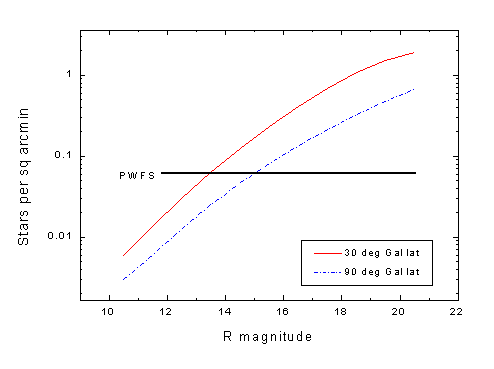
The two diagrams below show the surface density of stars as a function of optical R band magnitude for Galactic latitudes of 30 and 90 deg. They were derived from a Bahcall - Soneira model (e.g. Bahcall & Soneira 1984, ApJS, 55, 67) modified by Doug Simons.
The horizontal lines indicate the reciprocal patrol area of various Gemini wavefront sensors. The point at which each line cuts the stellar density curve indicates the magnitude where, statistically, one star should lie within that WFS's patrol area.
For example, one star of magnitude R = 13.5 - 15 (depending on Galactic latitude) should be available within the Peripheral WFS patrol area (~14 arcmin diameter). This implies that PWFS guide stars for most science targets can be selected from the GSC1 catalogue which has a limit of approximately 14-15 mag.
The detailed patrol field and sensitivity of the PWFS are given in the PWFS overview; the performance of the instrument OIWFS and adaptive optics AOWFS are included with the details of the relevant instruments.
Several on-line guide star catalogue servers are available.
Guide Star Catalogs
Any of the optical catalogs searchable in the Observing Tool (UCAC4, UCAC3, PPMXL, NOMAD1, and GSC-2 ) are acceptable for selecting guide stars for the optical wavefront sensors. Our tests have shown that the catalog with the best combination of photometry, astrometry, and exclusion of extended sources is the UCAC4. Therefore, we recommend using this catalog whenever possible.
Deep catalogs such as GSC-2, PPMXL, or NOMAD1 are useful for selecting faint natural guide stars for use in the ALTAIR + laser guide star mode.
The near-IR 2MASS catalog must be used for selecting guide stars for the near-IR on-instrument wavefront sensors in NIFS or GNIRS. This catalog should not be used to select stars for the optical WFS.
Adaptive Optics
![M2-9 with Adaptive Optics. Click to view larger image. [M2-9 with AO]](http://www.gemini.edu/images/pio/20080825_m2-9_0001.jpg) |
Adaptive optics (AO) forms an integral part of the Gemini telescopes' current and future suite of instrumentation. The facility AO system, ALTAIR, has been offered at Gemini North since 2003 and is now available for use with both natural and laser guide stars with NIRI and NIFS.
At Gemini South, Gemini Multi-Conjugate Adaptive Optics System (GeMS) with FLAMINGOS-2 and the Gemini South Adaptive Optics Imager (GSAOI) provides uniform, diffraction-limited image quality to arcminute-scale fields of view (download the science case for MCAO).
The pages in this section are organized as follows:
- Link to GeMS (GS)
- Link to GPI (GS)
- Link to ALTAIR (GN)
- Link to Laser guide star (GN)
- Link to Natural guide star usage (GN)
- Link to Adaptive Optics Image Gallery
Calibration Unit (GCAL)
A Gemini Facility Calibration Unit (GCAL) is available on each Gemini telescope, providing continuum and line emission light sources for wavelength and flat-field calibrations. Each GCAL is located permanently on one port of the instrument support structure and light is directed into an instrument by the science fold mirror. The GCAL optics simulate the f/16 telescope beam, illuminating the instrument pupil in the same way as light from an astronomical source. Instruments within the wavelength range 0.3µm - 5mm can be calibrated; mid-IR instruments are calibrated by other means.
GCAL is operated via flat and arc observations defined in the OT as part of each program's Phase II definition. Proper selection of lamps, ND filters and exposure times depends on the instrument being used and more information is available on the individual instrument web pages. The available line and continuum calibration lamps are shown in the table below.
| Lamp Name | Typical Usage | Lamp Type/Model | Example Spectra |
| Arc Line Lamps | |||
| Argon | Near-IR spectra |
Pencil lamp, Oriel 6030 |
GNIRS and NIRI spectra and line IDs |
| Xenon | Near-IR spectra | Pencil lamp, Oriel 6033 | GNIRS spectra and line IDs |
| ThAr | High-res optical spectra (to 50,000) |
Hollow cathode lamp, Cathodeon 3UAX Th |
|
| CuAr | Optical spectra | Hollow cathode lamp, Cathodeon 3UAX Cu | GMOS spectra and line IDs |
| Continuum Lamps | |||
| Quartz Tungsten Halogen (QTH) | Optical/Near-IR flat fields |
5W QTH bulb, Osram Halostar Starlite 64405S 5W 12V G4 (GS only) 100W QTH bulb, Osram HLX 64625 |
|
| Grey body (1100K) | Near-IR flat fields | Oriel 6580 | |
Notes: In March 2005 Krypton lamp replaced with Xenon for higher line density. GS ThAr lamp was removed for 100W QTH required for PHOENIX (visiting instrument) but the lamp is still in inventory.
Filters: A single eight-position filter wheel with ND and CB filters is available in the GCAL unit for flux attenuation and for flux gradients reduction of the QH lamp. Filters include ND1.0, ND2.0, ND3.0, ND4.0, ND4-5, GMOS CB and NIR CB.
Diffusers: Visible and IR diffusers are provided. Note the IR diffuser has two emission lines that may affect flats, as was observed on GMOS.
Intensity stability: The intensity stability of the Grey Body source reflects the stability of the power supply and is expected to be ±1%. The intensity stability of the QH lamp (from the manufacturers’ specification) is ± 0.4% rms.
Output beam stability: The original instrument requirement states that the output beam should be flat with a monotonic roll-off in intensity of <10% to the edge of the 7' diameter field, and that variations over the 3’ field should be 1%. To achieve a flatter beam than this requires calibration of the GCAL against the sky with each of the instruments.
Documentation
The primary GCAL design references are the Functional and Performance Requirements and Operational Concepts Definition Documents.
An early paper describing aspects of GCAL is: "Dedicated calibration facility for the Gemini Telescopes", Ramsay Howat, S. K., Harris, J. W., Bennett, R. J. (1997) SPIE, 2871, 1171.
The basic performance requirements are defined in the Science Requirements Document that guided overall telescope design and construction (frozen at SRD 3.0; 130k PDF) e.g., pointing, tracking, guiding, chopping, intrinsic image quality in the absence of atmosphere, etc.