Announcements
Instrument capability
GHOST performs echelle spectroscopy between 347 and 1060nm, for a single target with spectral resolution (R) around 76,000 (in the high resolution mode), and for either one or two targets (separated by at least 102 arcsec) with R of around 56,000 (the standard resolution mode). A description of the capabilities of each mode, and the instrument, follows.
| Table 1: GHOST operational modes | ||||||
|---|---|---|---|---|---|---|
| Mode | Standard resolution | High Resolution | ||||
| Spectral coverage | 347-1060 nm (simultaneous); 383-1000 nm (usable) | 347-1060 nm (simultaneous); 383-1000 nm (usable) | ||||
| Spectral resolution | 56000 | 76000 | ||||
| Binning modes | 2,4,8 (spatial); 2, 4 (spectral) | 2,4,8 (spatial); 2, 4 (spectral) | ||||
| Radial velocity precision | 600 m/s | 10 m/s | ||||
| Multiplexing | Two targets (minimum separation 102arcsec) or single target | Single target | ||||
| Field of view | 7.34 arcmin (overlap of two IFUs 16arcsec) | 7.34 arcmin | ||||
| IFU aperture | 0.94 arcsec^2 | 0.92 arcsec^2 | ||||
| Sky aperture | 0.4 arcsec^2 | 0.34 arcsec^2 | ||||
| Microlens configuration | 7 microlenses in each object IFU | 19 microlenses in object IFU | ||||
| 3 microlenses in sky IFU | 7 microlenses in sky IFU | |||||
| Calibration source | None | Internal ThXe lamp | ||||
| Limiting magnitude | V ~ 20.8 mag | V ~ 19.6 mag | ||||
- Standard resolution mode allows users to obtain single or dual target spectra with resolving power greater than 50,000, depending on the wavelength in question. A series of hexagonal microlens form an input light aperture of diameter 1.2" at the maximum, are arranged into seven constituent microlens increasing the resolution by a factor of 3. Dual targets must be separated by at least 102", and lie within a circular area of 7.34'. While sky subtraction is afforded by a dedicated sky IFU, located 3.3" away in the IFU1 probe arm, one can also adopt the second standard resolution IFU for better sky subtraction, for e.g. in crowded fields, or extended objects.
- This mode is recommended for most science cases needing high resolution, but also the increased throughput if observing faint targets (V-band ≤ 19 mag), or needing the sky subtraction for crowded fields.
- High resolution mode allows users to obtain single target spectra with resolving power greater than 75,000, depending on the wavelength in question. The maximum width of the input aperture remains the same as the standard resolution slit, however the final image is increased by a factor of 5, providing similar resolution to a slit of width of 0.24 arcsec. Dedicated sky fibres located 3 arcsec away provide sky subtraction.
This mode is recommended for science cases that desire the extra gain in resolution, at the loss of throughput, particularly at the blue end. Faint targets (with V-band magnitudes greater than 16 mag) are not recommended for this mode. An example of absolute flux calibrated spectra of the T Tauri star TW Hya taken in high resolution is shown below.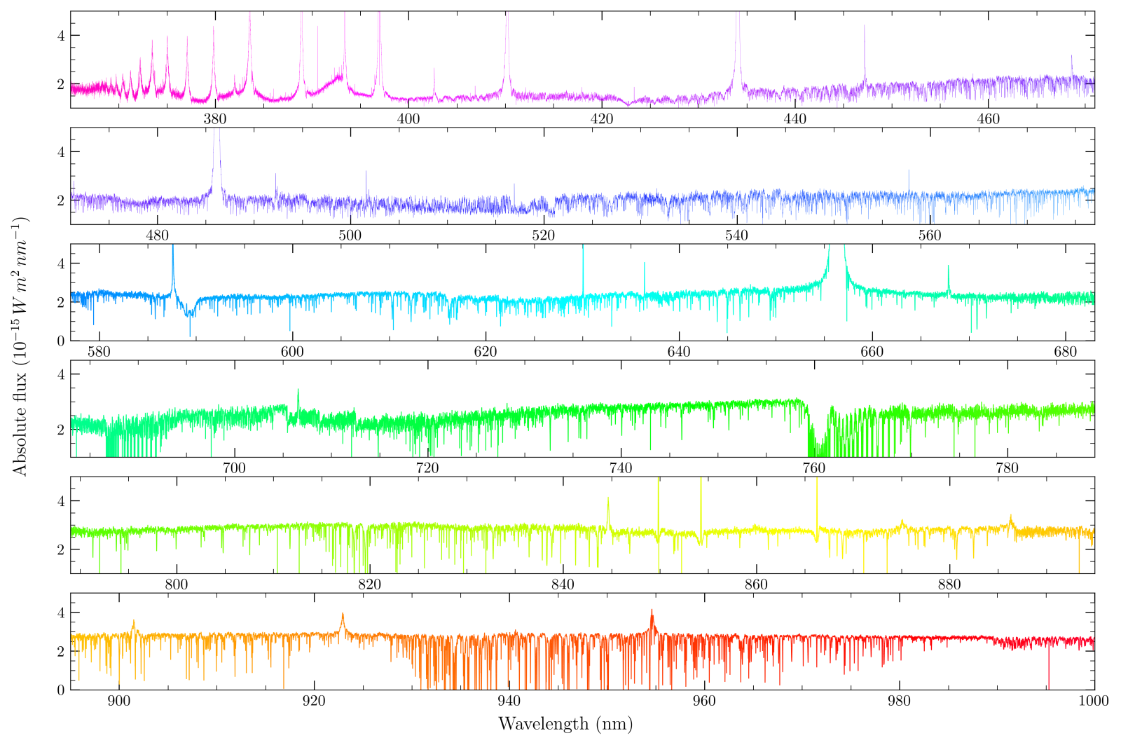
An example of absolute flux calibrated spectra taken in the high resolution mode of the T Tauri star TW Hya is shown for an illustration of the quality of spectrum obatined with GHOST. - Precision radial velocity mode allows users to obtain high resolution spectra, along with a simultaneous ThXe calibration source, allowing users to reach radial velocity precisions of few tenths m/s. This mode is not currently offered.
Field of view and slit unit
The Cassegrain unit is mounted on the telescope. It contains the two robotic probe arms each carrying one IFU head, which in turn contain 2 or 3 individual IFUs. From the IFUs a 32m fiber cable runs to the spectrograph in the pier laboratory. The total field of view covered by the cassegrain unit probe arms is 7.34 arcmin, with each covering a semicircle of diameter 3.7 arcmin. The minimum separation between dual targets is 102 arcsec. Interested users can check the feasability of observing their targets using the Gemini Observing tool.
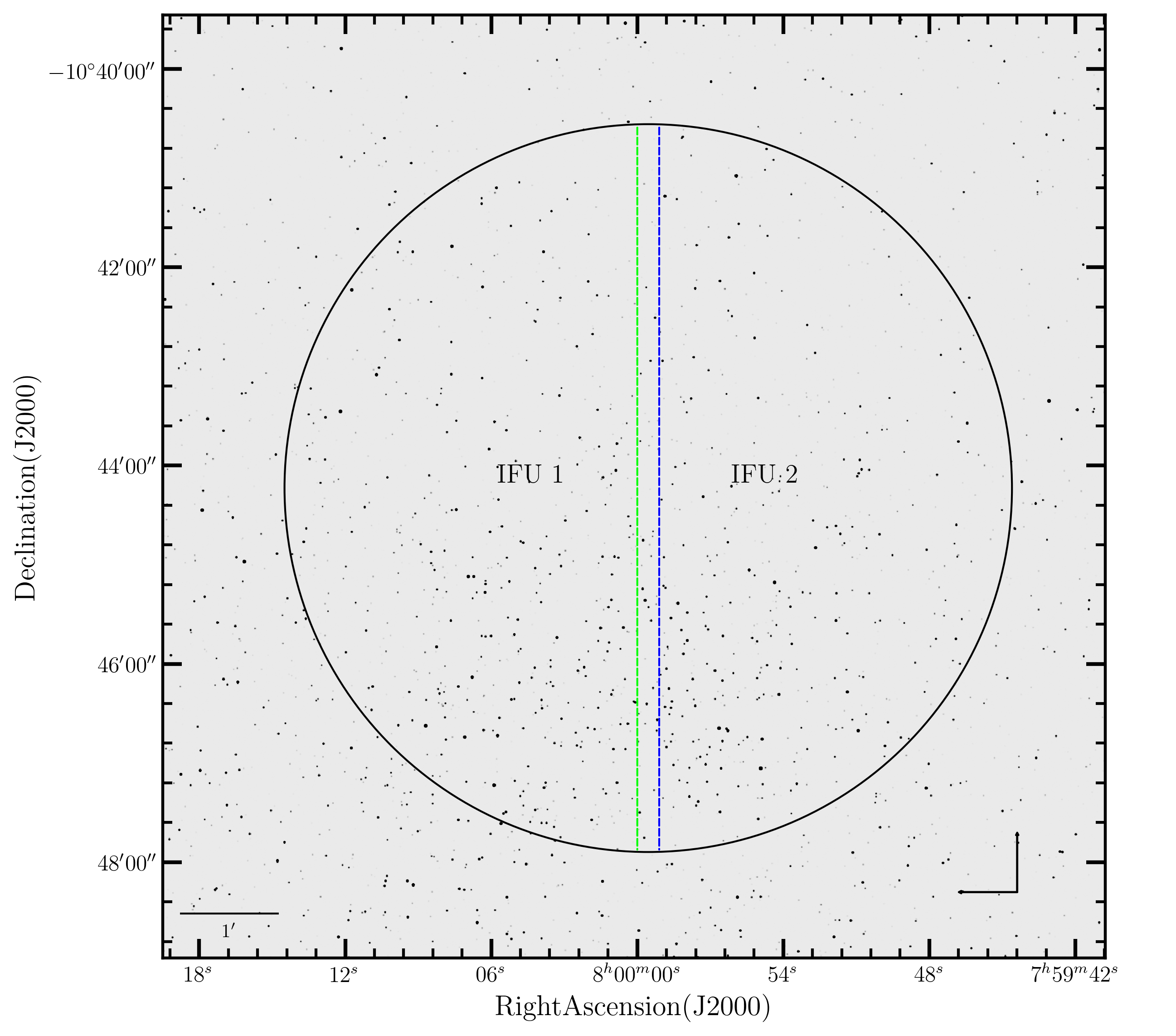
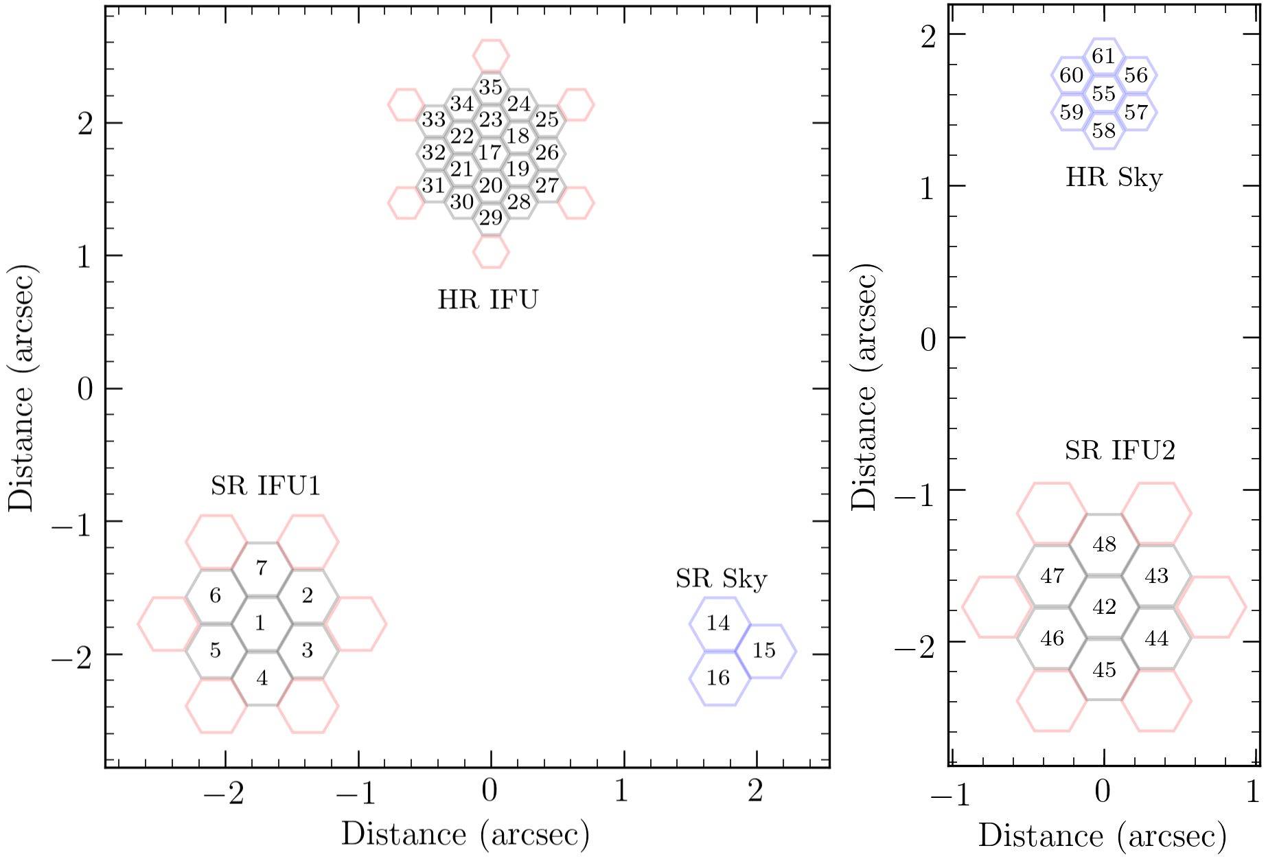
The positions, and metrology of each individual probe arm is shown below. Each standard resolution IFU covering 0.94 arcsec2 on the sky, with a dedicated sky IFU covering 0.4 arcsec2. The high resolution IFU covers a total aperture of 0.92 arcsec2, with the high resolution sky IFU having an area of 0.34 arcsec2. The IFU areas are not circularly uniform, but are best approximated by the hexagonal area displayed. The position of the dedicated sky IFUs can be seen in the Gemini OT. Each probe arm also has a dedicated atmospheric dispersion corrector (ADC). These provide corrections for airmasses up to 2, allowing significantly better blue throughput at lower airmasses.
Since the focal plane of the unit does not allow for movement along the applicate axis, the telescope software corrects for loss of focus across the focal plane, by defocussing each IFU based on distance from the centre of the focal plane. This leads to small slit lossses (typically around a few percent) when compared to the centre. Due to this effect, it is preferred that single target objects are observed at the centre of the focal plane whenever possible, and dual targets are best observed at radially symmetric positions from the centre.
The integrated FWHM (full width at half maximum) of each IFU is measured when light is passed from the fibre cable to a slit unit, containing two broadband filters having transmissions between 420-600nm, and 600-760nm. This allows measurement on object of the full-width half maximum, which are corrected for zenith distance and wavelength to determine the IQ percentile bin during nigth time obsrevations. Given the fixed limited aperture, slit losses become significant at IQ greater than IQ85, and poor seeing spectroscopy is mostly viable only for bright objects. The psuedos-slit is essential for obtaining radial information which is scrambled during fiber transmission.
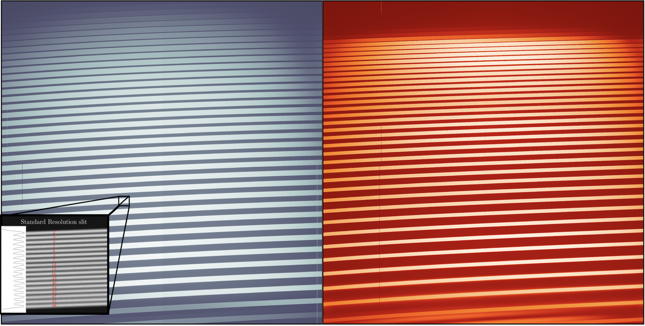
The final image from the IFUs before passing to the slit unit is sliced by the width of each individual microlens, thereby increasing the spectral resolution by a factor of 3 and 5 for the standard and high resolution cases respectively. Each microlens in the probe arm can be identified in the final slit image, and are shown below. The final image of formed at the psuedo-slit is in principle not horizantally aligned, but titled by around 9 degrees, and this involves a further correction accounted for in the data reduction.
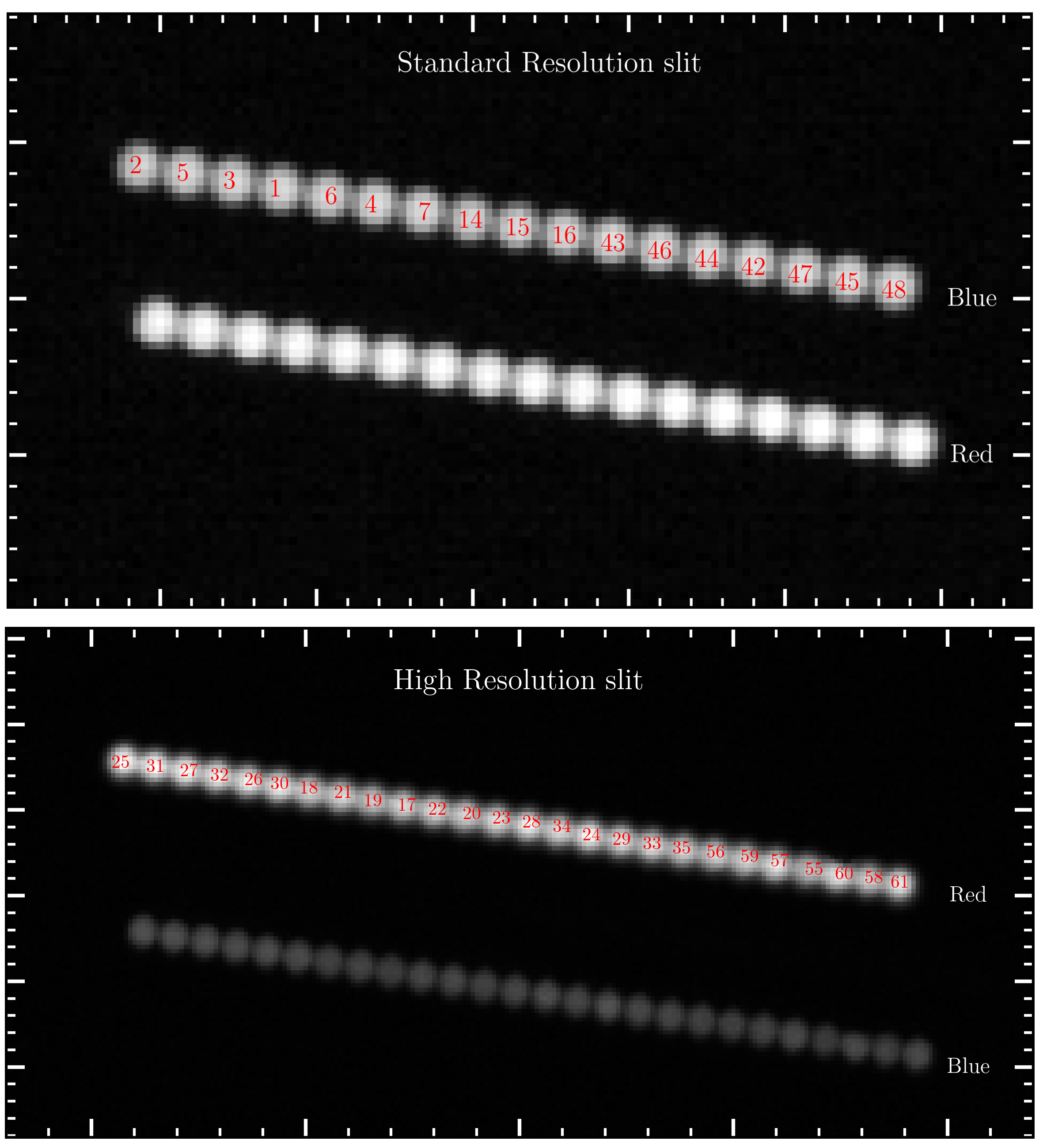
The final spectra preserves the arrangment of the slit, and is demonstrated with each individual fiber marked. The final spectral format, and the detector properties can be found in the data reduction and components webpages.
Spectral Range and Resolution
The full GHOST spectral wavelength coverage is 347-1060nm, but the useful range is 383-1000nm (below which the throughput of the instrument falls below 2%). GHOST has only one moving part, the slit mask positioner (essentially switching between standard, and high resolution slits), and rests inside an actively controlled and monitored thermal and pressure enclosure. Shown below are spectral orders and the respective central wavelength in echelleogram format in both the red, and blue detectors.
The spectral resolution is calculated based on lines of an observed ThAr lamp spectrum. The average resolution element in SR mode was determined to be 2.8 pixels, with a overall resolving power of R around 56000 in blue, but slightly higher in red. In the HR mode, 1.8 pixels is the average per resolution element, overall resulting in a minimum resolving power of at least 76,000. A detailed estimate of the spectral resolution order by order may be found in McConnachie et al. (2024). Below are shown the spectral resolution as a function of wavelength.
Binning Options
GHOST offers 8 different on-chip binning options: 1x1, 1x2, 1x4, 1x8, 2x2, 2x4, 2x8, 4x4 (spectral x spatial). While the ideal binning option may differ for different science cases, Table 1 (below) lists the recommended binning options for the major operational modes of GHOST. Note that 8x binning in the spatial direction is only recommended for single-object modes, as extreme spatial binning can merge objects.
| Table 1: Recommended binning for main GHOST operational modes | ||||||
|---|---|---|---|---|---|---|
| Operational mode | Resolution mode | On-chip binning | Notes | |||
| Dual target | Standard resolution | 1x2, 1x4, 1x8, 2x2, 2x4 | ||||
| Single target, faint | Standard resolution | 2x8* | *Only suitable for single object since extreme spatial binning merges objects. Trade-off of read noise versus extra sky in object pixels | |||
| Single target | High resolution | 1x2, 1x4, 1x8 | ||||
Throughput
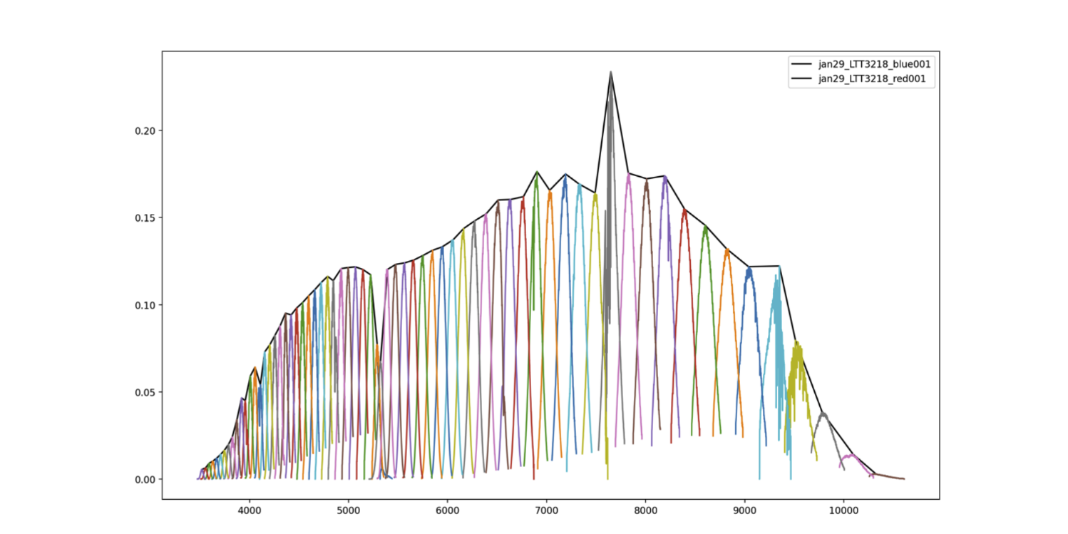
Example of the throughput calculated for a blue and a red exposure of LTT3218 on January 29 2023. Individual orders are plotted, as are black lines that trace the peak throughput in each order. The y-axis displays throughput, and the x-axis displays wavelength in Angstroms.
The throughput is depending on the atmospheric conditions and a change in just 0.1 arcsec in the FWHM of a stellar image can result in additional slit losses of order 10%
Sensitivity
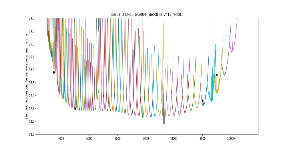
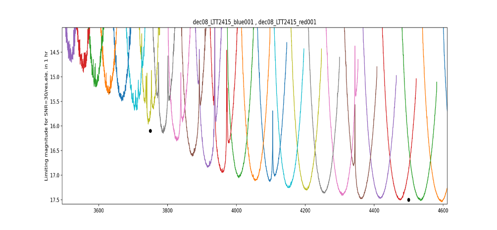
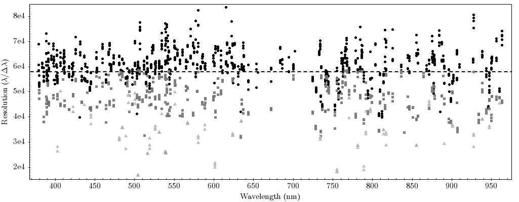
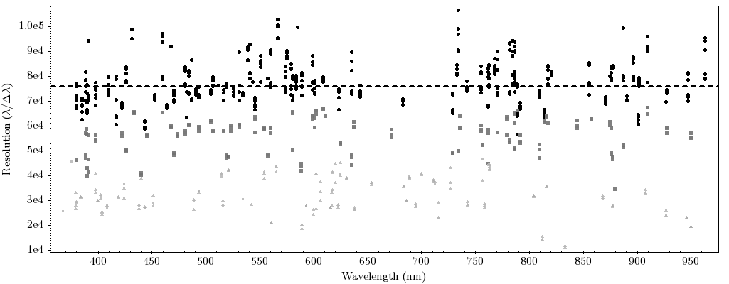
Magnitude corresponding to SNR=30 per resolution element as a function of wavelength for the December 8 2022 observation of LTT2415. Only values at the order centres are relevant. Black points indicate requirements, where the nearest order center should meet or exceed this value. Top panel shows the entire GHOST wavelength range. Bottom panel shows a zoom in at blue wavelengths. In both plots, the y-axis displays the limiting magnitude for SNR=30/resolution element in 1 hour, and the x-axis displays the wavelength in Angstroms.
GHOST achieves a sensitivity of AB mag = 17.5 (450nm), 15.3 (363nm), 16.1 (375nm), 17.0 (550nm), 17.2 (900nm) and 16.2 (950nm) in a 1 hour observation for 30 sigma per resolution element in standard resolution mode in dark time (SB50), clear sky conditions (CC50) and nominal image quality (IQ70).
Radial velocity performance
The radial velocity uncertainities from repeated high signal to noise observations of radial velocity standards are around 100-30 m/s. The team at Gemini is conducting observations of radial velocity standards whenever the instrument is on sky, and results from the initial monitoring program will be released shortly. The average pixel drifts as a function of pressure (and to a lesser degree temperature) across 15 hours is less than 0.2 pixels.
Guiding Options
The guiding is performed using the Peripheral Wavefront Sensors (PWFS2), with additional fine guiding provided by the instrument microlenses. In general, there must be a Peripheral wave front sensor guide star within 6.75 arcmins for two IFUs, (and for a single target within 9.85 arcmins). This is used to acquire the base position of the focal plane, and center the science IFUs.
The guide fibers of the instrument are used to center before an exposure, correcting for small probe-mapping errors, or flexure with the telescope guiding. This guiding, along with P2WFS is monitored over the duration of the exposure, providing small corrections to the positioners to keep IFU well centered. The probe mapping is currently precise enough that most targets, across the focal plane are captured in both IFUs within pointing errors of the P2WFS (0.2 arcsecs).