Announcements
Optical Design
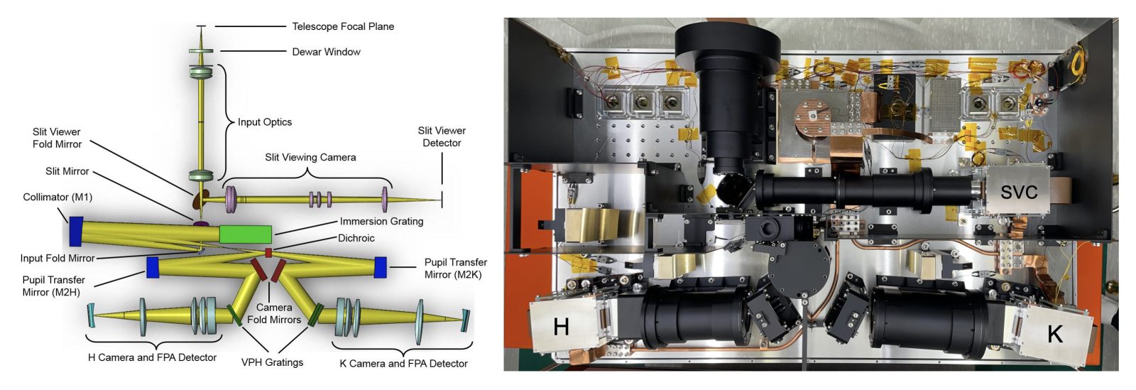
The IGRINS-2 optical system is designed to achieve a broad simultaneous wavelength coverage while maintaining a spectral resolving power of ~45,000. The IGRINS-2 optical layout is shown in Figure 1.
The input optics reimage the telescope pupil onto a cold stop before refocusing it onto the slit plane. The light reflected by the slit mirror is directed to the slit viewing camera, while the light passing through the slit is collimated by an off-axis mirror before reaching the immersion grating. The dispersed beam is then collimated again and directed to a high-efficiency dichroic, which splits the light between the H and K arms of the spectrograph. Each of the H and K beams is subsequently collimated, cross-dispersed, and directed into the refracting cameras, where they reach the detectors.

Figure 1: Optical layout (left) and full assembly (right) of the IGRINS-2.
Detector Array
IGRINS-2 utilizes two Teledyne HAWAII-2RG (H2RG) spectrograph detector arrays, each featuring a 2048x2048 configuration. The outer four pixels on each side are not illuminated and serve as reference pixels, resulting in an effective active area of 2040x2040 pixels. The properties of the HAWAII-2RG (H2RG) detector arrays for the IGRINS-2 are given in the table below.
| Table 1: IGRINS-2 Detector Characteristics | ||
| Detector Array | Teledyne HAWAII-2RG (H2RG) HgCdTe | |
| Pixel format | 2048 x 2048 18 micron pixel | |
| Pixel Scale | 0.1" | |
| H | K | |
| Dark Current | 0.0225 e-/s/pixel | 0.04 e-/s/pixel |
| Gain | 2.5 e-/ADU | 2.5 e-/ADU |
| Quantum efficiency | > 80% | > 80% |
| Well depth | 40,000 ADU (100,000 e-) | 52,000 ADU (130,000 e-) |
The H2RG detector is capable of detecting light out to 2.6 um, and employs a HgCdTe detector layer. Instead of using a traditional shutter to control exposure duration, the detector captures images by measuring the difference in signal between two readouts: one at the start and one at the end of the integration. Consequently, the minimum exposure time is constrained by the readout time. To minimize read noise, the Fowler sampling is used, which averages several reads to enhance data quality.
| Table 2: IGRINS-2 Detector Read Modes | |||
| Number of Fowler Samples | Readout Overheads (sec) | Read noise (e-) | |
| H | K | ||
| 1 | 10.0 | 17.6 | 23.9 |
| 2 | 12.8 | 12.4 | 17.0 |
| 4 | 17.4 | 9.0 | 12.3 |
| 8 | 25.3 | 6.5 | 8.9 |
| 16 | 41.0 | 5.2 | 6.7 |
Gratings
IGRINS-2 uses a silicon immersion echelle grating as the main disperser and volume phase holographic (VPH) gratings as the cross-dispersers. The instrument covers the H and K bands simultaneously in a single exposure.
| H | K | |
| Central wavelength | 1.65 um | 2.20 um |
| Wavelength coverage | 1.49 - 1.80 um | 1.96 - 2.46 um |
| Spectral resolution | 50,000 | 45,000 |
| Orders | 122 to 98 | 92 to 71 |
Slit
IGRINS-2 has a single slit with a size of 0.33" x 5".
Slit Viewing Camera (SVC)
IGRINS-2 is equipped with a Slit Viewing Camera (SVC), which considerably reduces acquisition times and permits real-time monitoring of the telescope tracking and guiding performance.
| Field of View | 46" diameter | |
| Color Filter | Ks | |
| Plate Scale | 0.04 "/pixel | |

Figure 2: SVC image of the Orian BN field, with a slit shown in the center.